Apparatus for cooling electric motors

a technology for electric motors and accessories, applied in the direction of electric propulsion mounting, transportation and packaging, propulsion parts, etc., can solve the problems of increasing the overall dimensions and overall weight of the drive, increasing the overall weight of the vehicle as a whole, and requiring additional space, so as to achieve easy assembly and disassembly of the whole axle, the effect of reducing the need for space and weight advantag

Inactive Publication Date: 2016-02-02
ZF FRIEDRICHSHAFEN AG
View PDF16 Cites 8 Cited by
  • Summary
  • Abstract
  • Description
  • Claims
  • Application Information

AI Technical Summary

Benefits of technology

[0012]The use of a single cooling fluid connection line saves weight on the one hand, since using two cooling fluid lines per electric motor for the arranged cooling fluid pump or cooling fluid reservoir, which may be removed, can be dispensed with. In addition, this allows for cooling devices with a smaller solid measure, so that such cooling devices, and thus also the electric motors, can be housed more easily close to the wheels. Moreover, eliminating additional cooling fluid lines reduces the risk that such cooling fluid lines leak, and that sufficient cooling of the electric motors can no longer be provided.
[0014]In a particular configuration, preferably, at least two electric motors are arranged on a torsion beam. Thereby, the torsion beam may consist of at least two trailing arms, with a wheel arranged on each, and with a cross beam that connects the two trailing arms to each other. A trailing arm is a component that extends at least roughly parallel to the longitudinal axis of the vehicle, and is flexibly connected to the car body and the wheel. A cross beam is a component that connects the two longitudinal beams, whereas the contact points between the cross beam and the trailing arms are each spaced along the car body. The main direction of propagation of the trailing arm lies parallel to the longitudinal axis of the vehicle; the main direction of propagation of the cross beam is correspondingly arranged crosswise on this. Such torsion beams are particularly used for the rear axle, and allow for easy assembly and disassembly of the whole axle, and have little need for space and only a few components. The arrangement of the electric motors on the torsion beam makes it possible to arrange the electric motors in fixed positions relative to the wheels, such that the spring movement does not give rise to a shift in the position of the drive wheels with regard to the electric motors.
[0015]Preferably, the cooling fluid connection line is arranged on the cross beam. Thus, the cross beam that connects the two trailing arms with each other can be connected to the cooling fluid connection line, in order to hold and / or support the cooling fluid connection line. In doing so, less solid, thinner and, in particular, lighter cooling fluid connection lines can be used, resulting in a further weight advantage. In particular, the cooling fluid connection line can be welded, screwed together and / or glued with the cross beam. In particular, the cooling fluid connection line can, at least partially, at least substantially, run parallel to the cross beam.
[0016]Moreover, the cooling fluid connection line can be arranged in the cross beam, such that the cross beam at least partially surrounds the cooling fluid connection line. Thus, through the solidly constructed cross beam, the cooling fluid connection line can be protected from damage. Moreover, the cooling fluid connection line can feature less weight, since it is possible to use thinner and thus lighter walls.
[0017]In particular, the cooling fluid connection line forms the cross beam, by which separate cooling fluid connection line walls are unnecessary, and thus the cooling fluid connection line can be formed with even less weight.
[0018]The cross beam can be made of metal, such as steel, and / or other materials, such as plastic, glass fiber reinforced plastic and / or carbon fiber reinforced plastic. Such materials have a sufficiently high resistance, on the one hand in order to be used as a fluid conductor; on the other hand, these materials allow for a cross beam with a low weight.

Problems solved by technology

However, such cooling devices represent an additional weight and require additional space, thus increasing the overall dimensions and overall weight of the drive and thus of the vehicle as a whole.

Method used


Image

  • Apparatus for cooling electric motors
  • Apparatus for cooling electric motors
  • Apparatus for cooling electric motors

Examples


Embodiment Construction

[0025]Reference will now be made to embodiments of the invention, one or more examples of which are shown in the drawings. Each embodiment is provided by way of explanation of the invention, and not as a limitation of the invention. For example features illustrated or described as part of one embodiment can be combined with another embodiment to yield still another embodiment. It is intended that the present invention include these and other modifications and variations to the embodiments described herein.

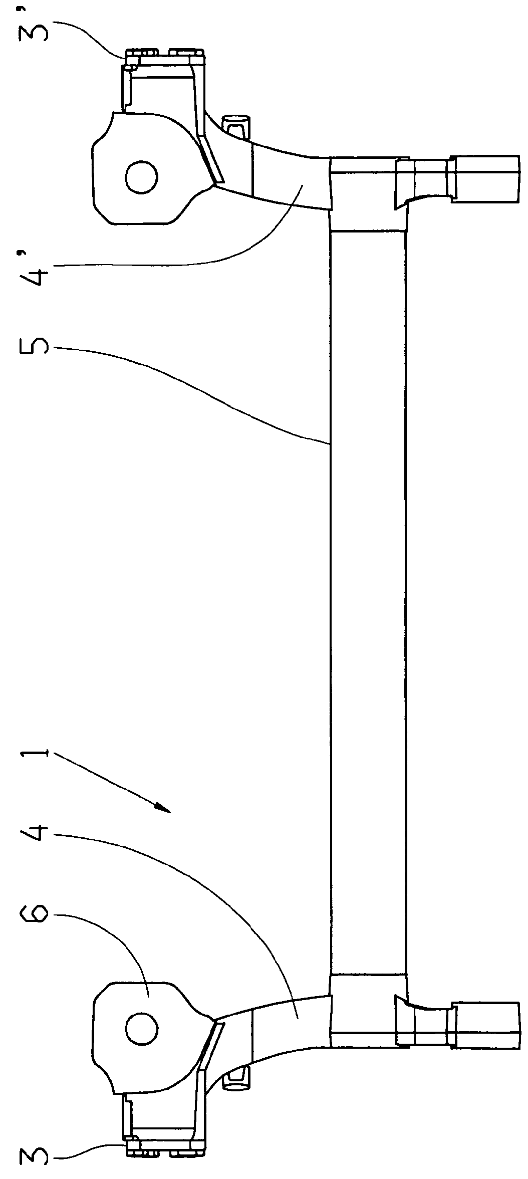
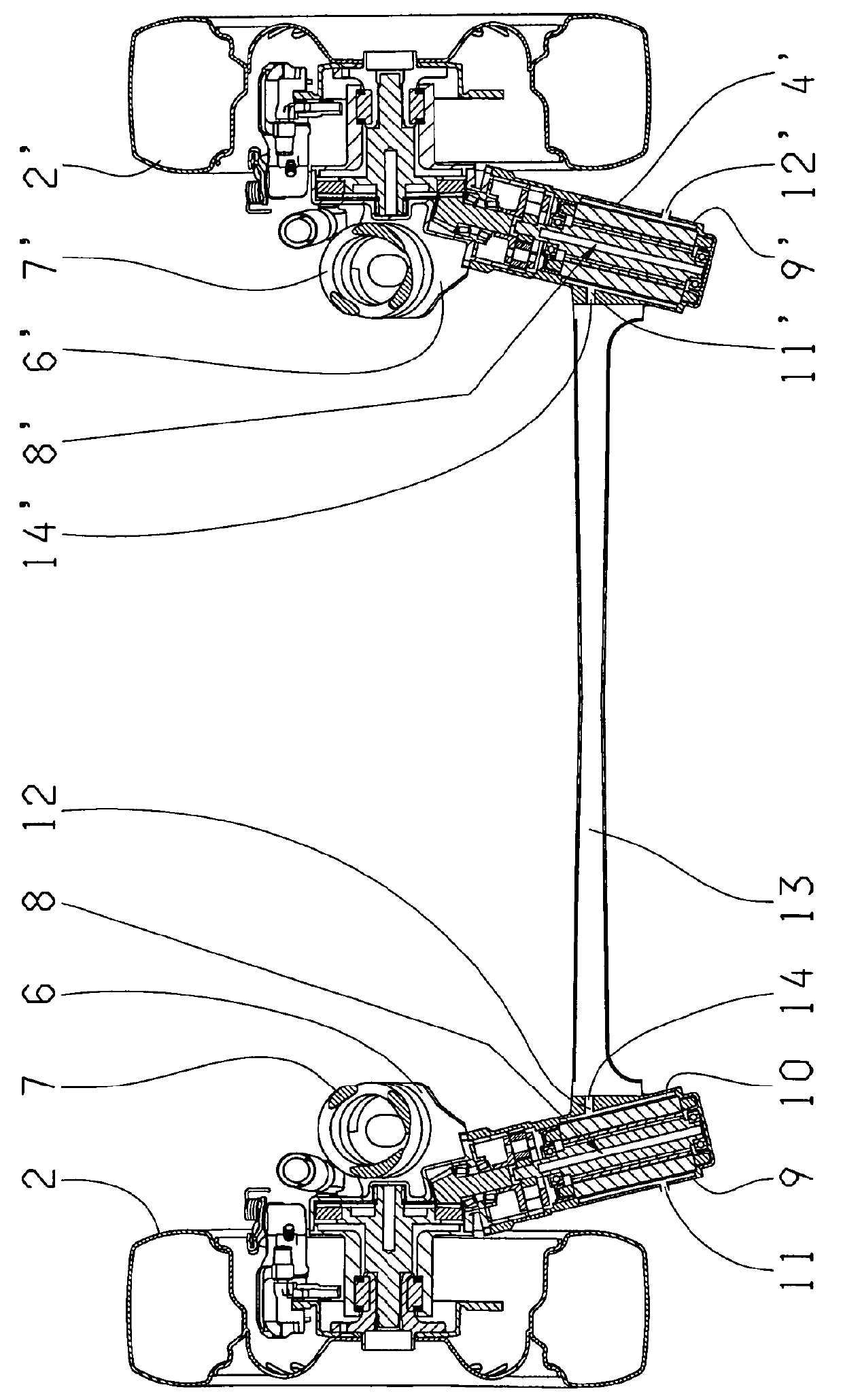
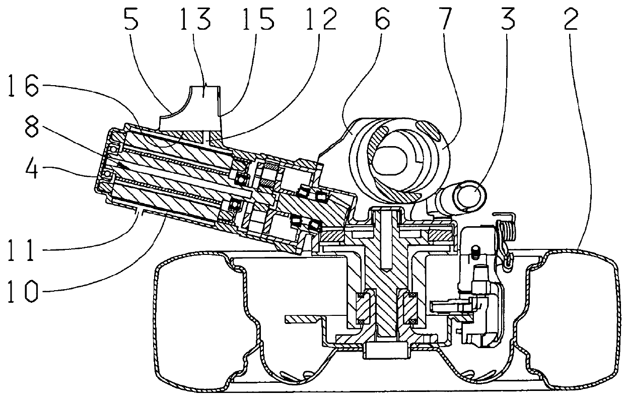
[0026]FIG. 1 shows a torsion beam 1, as it can be used as the rear axle in small vehicles. The torsion beam 1 connects the two wheels 2, 2′ (FIG. 2) and thereby allows the compression of the wheels 2, 2′. The wheels 2 are thereby rotatably attached to the trailing arms 4. Further, the torsion beam 1 comprises a cross beam 5, which connects the two trailing arms 4, 4′ to each other, and thus stabilizes the wheel position. The cross beam 5 is thereby enclosed in nearly a right angle ...


PUM


Abstract

A device for propelling a vehicle includes at least two electric motors, whereas each of the electric motors is equipped with a cooling device. The cooling device includes at least one cooling fluid line, whereas the cooling fluid lines are connected to the two cooling devices through a common cooling fluid connection line.

Description

FIELD OF THE INVENTION[0001]The invention is concerned with a device for propelling a vehicle, comprising at least two electric motors, whereas each of the at least two electric motors is equipped with a cooling device that includes at least one cooling fluid line. Furthermore, the present invention is concerned with a vehicle equipped with the electric motors and cooling devices.BACKGROUND[0002]Increasingly, electric motors are used to propel vehicles. Vehicles in which electric motors provide the propulsion together with motors of other designs, such as internal combustion engines, as well as vehicles in which only electric motors are used for propulsion, are customary.[0003]In the course of further development and the reduced dimensions of the electric motors that this has brought about, it is possible to use, instead of one powerful centrally arranged electric motor, which takes effect on at least one drive axle, several smaller electric motors, such that one electric motor can ...

Claims


Application Information

Patent Timeline
Patent Type & Authority Patents(United States)
IPC IPC(8): B60K11/02B60K17/356B60K7/00H02K9/19B60K17/04B60K11/00B60K1/02B60C23/18B60K1/00
CPCB60K11/02B60C23/18B60K1/02B60K7/0007B60K11/00B60K17/043B60K17/356H02K9/19B60K2001/006B60K2007/0038H02K5/203
Inventor MAIR, ULRICHHEIMANN, JENS
Owner ZF FRIEDRICHSHAFEN AG
Why Eureka
Try Eureka