Hydraulic circuit for pipe layer

a technology of hydraulic circuit and pipe layer, applied in the direction of fluid coupling, servomotor, coupling, etc., can solve the problems of pressure rising and generation of chattering, and achieve the effect of preventing chattering and improving manipulability

Active Publication Date: 2016-02-02
VOLVO CONSTR EQUIP AB
View PDF13 Cites 13 Cited by
  • Summary
  • Abstract
  • Description
  • Claims
  • Application Information

AI Technical Summary

Benefits of technology

[0045]The hydraulic circuit for a pipe layer in accordance with an embodiment of the present invention as constructed above has the following advantages.
[0046]It is possible to prevent chattering and occurrence of hydraulic shock in equipment due to a pressure rise caused by an excessive flow rate of a hydraulic fluid discharged from the hydraulic pump when a work apparatus or a traveling apparatus is finely manipulated during a combined operation in a pipe-laying operation mode, thereby improving manipulability.

Problems solved by technology

For this reason, the conventional the hydraulic circuit for a pipe layer entails a problem in that the discharge flow rate of the hydraulic pumps is controlled to the maximum in terms of the characteristics of the negative flow control system to cause the pressure to rise due to the excessive flow rate of the hydraulic fluid discharged from the hydraulic pump, leading to generation of chattering.

Method used


Image

  • Hydraulic circuit for pipe layer
  • Hydraulic circuit for pipe layer
  • Hydraulic circuit for pipe layer

Examples


Embodiment Construction

Technical Problems

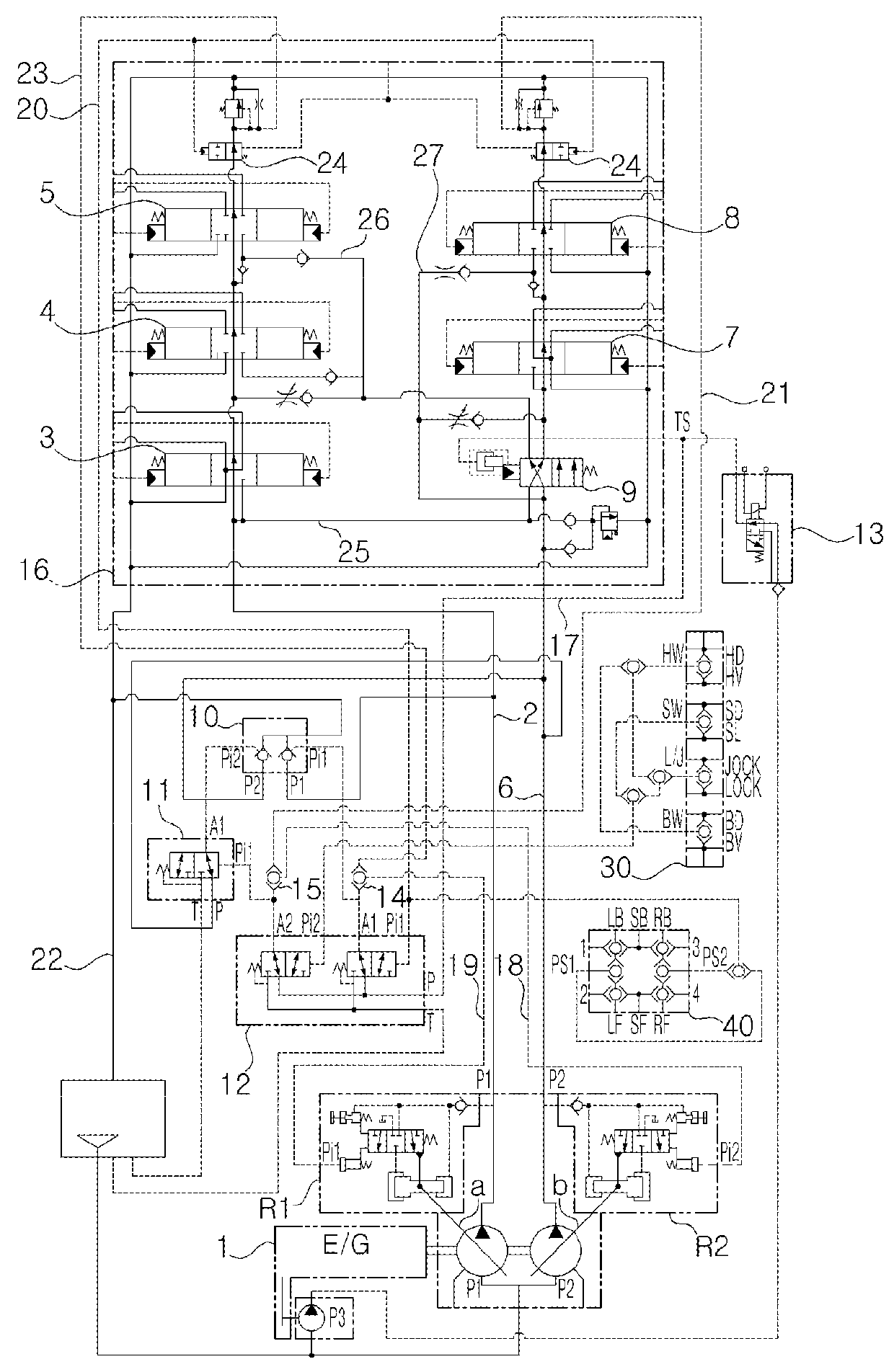
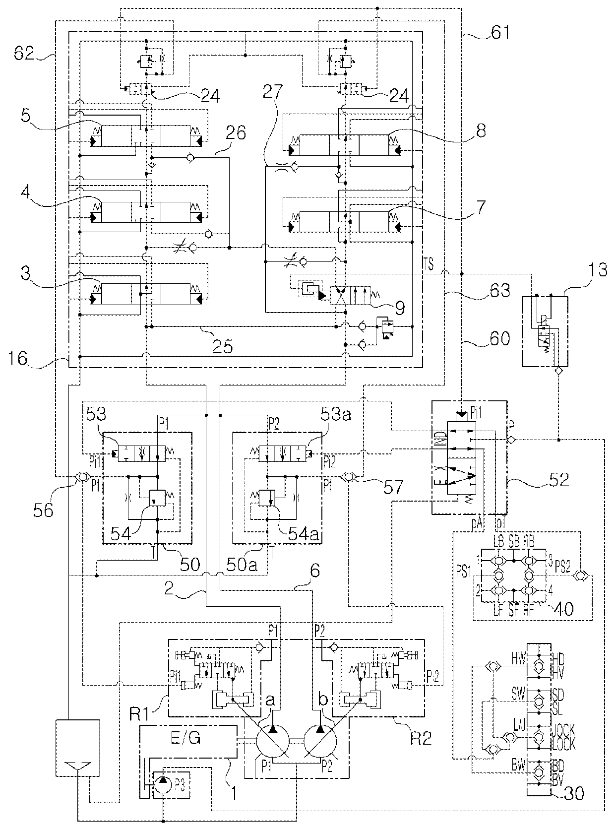
[0029]Accordingly, the present invention has been made to solve the aforementioned problem occurring in the prior art, and it is an object of the present invention to provide a hydraulic circuit for a pipe layer, in which when a work apparatus or a traveling apparatus is finely manipulated during a combined operation in a pipe-laying operation mode, hydraulic shock in equipment due to an excessive flow rate of a hydraulic fluid discharged from the hydraulic pump is prevented from occurring, thereby improving manipulability.

Technical Solution

[0030]To accomplish the above object, in accordance with an embodiment of the present invention, there is provided a hydraulic circuit for a pipe layer, in which a discharge flow rate of a hydraulic pump is controlled by a negative flow control system, the hydraulic circuit including:

[0031]first and second hydraulic pumps and a pilot pump, which are configured to be connected to an engine;

[0032]one or more first control valves i...


PUM


Abstract

Disclosed is a hydraulic circuit for a pipe layer, in which the generation of hydraulic shock in equipment is prevented when an operating device or a moving device is finely operated during combined work in a pipe-laying operation mode. The hydraulic circuit for a pipe layer according to the present invention comprises a main control valve having a straight traveling valve and controls a discharged flow of a hydraulic pump by a negative flow control system, wherein the hydraulic circuit comprises: an unloading valve which linearly controls the closing of a passage of a flow that flows to a hydraulic tank from a center bypass passage of a hydraulic pump when an operating device or a moving device is finely operated during combined work; a pilot valve which is linked with a straight traveling valve, and supplies signal pressure corresponding to an operation signal of the moving device or the operating device to the unloading valve; and an operation mode switch valve which is switched during the combined work, and respectively supplies pilot signal pressure to the straight traveling valve, the pilot valve, and a valve spool which is installed on a downstream side of the center bypass passage of the hydraulic pump.

Description

FIELD OF THE INVENTION[0001]The present invention relates to a hydraulic circuit for a pipe layer employing a negative flow control system. More particularly, the present invention relates to a hydraulic circuit for a pipe layer, in which when an actuator (or a boom cylinder, or the like) for work apparatus is finely manipulated in a pipe-laying operation mode (PL mode: a work mode in which a pipeline or the like is lifted and transported to a burial place), a hydraulic shock can be prevented from occurring.BACKGROUND OF THE INVENTION[0002]The above negative flow control system refers to a system in which when a pilot signal pressure generated from a pilot signal pressure-generating means installed at the downstream side of a center bypass path is high at the upstream side of the center bypass path, a discharge flow rate of a variable displacement hydraulic pump is controlled to be decreased whereas when the pilot signal pressure generated from a pilot signal pressure-generating mea...

Claims


Application Information

Patent Timeline
Patent Type & Authority Patents(United States)
IPC IPC(8): F16D31/02F15B11/17F15B11/16E02F9/22F15B15/18F15B13/08E02F5/10
CPCF15B11/17E02F5/10E02F9/2232E02F9/2242E02F9/2267E02F9/2282E02F9/2285E02F9/2292E02F9/2296F15B11/165F15B13/08F15B15/18F15B2211/20553F15B2211/20576F15B2211/3116F15B2211/329F15B2211/50536F15B13/043F16K11/07
Inventor JEON, MAN-SEUKCHOI, HAN-OK
Owner VOLVO CONSTR EQUIP AB
Why Eureka
Try Eureka