
Compressor discharge valve providing freeze and charge migration protection

a discharge valve and compressor technology, applied in the field of compressor discharge valves, can solve the problems of still occurring chatter and the drawback of control of the pillis valv

Active Publication Date: 2011-01-13
TRANE INT INC
View PDF5 Cites 11 Cited by
  • Summary
  • Abstract
  • Description
  • Claims
  • Application Information

AI Technical Summary

Benefits of technology

The present invention provides a compressor discharge valve that ensures proper oil return to the compressor at startup, prevents the evaporator from freezing when the system shuts down during low ambient temperature conditions, reduces chatter in the compressor discharge valve, and regulates discharge pressure by opening the valve at an intermediate position between the fully open and closed positions. The discharge valve also includes a stem guide and a valve plug that helps prevent the valve from rubbing against the endplate of the compressor's housing. The invention also provides a refrigerant system that includes the discharge valve and an oil separator for efficient oil return. The discharge valve ensures proper oil return to the compressor at startup and prevents the evaporator from freezing when the system shuts down during low ambient temperature conditions. The invention also provides a method for controlling the discharge valve without relying on solenoid valves.

Problems solved by technology

The addition of solenoid valve (46) and having to control it is a drawback of the Pillis valve.
Chatter might still occur, however, when the valve first begins opening.
A repeat of such a cycle in rapid succession can result in chatter.
Other causes of rapidly fluctuating discharge pressure can also be a source of valve chatter.

Method used


Image

  • Compressor discharge valve providing freeze and charge migration protection
  • Compressor discharge valve providing freeze and charge migration protection
  • Compressor discharge valve providing freeze and charge migration protection

Examples


Embodiment Construction

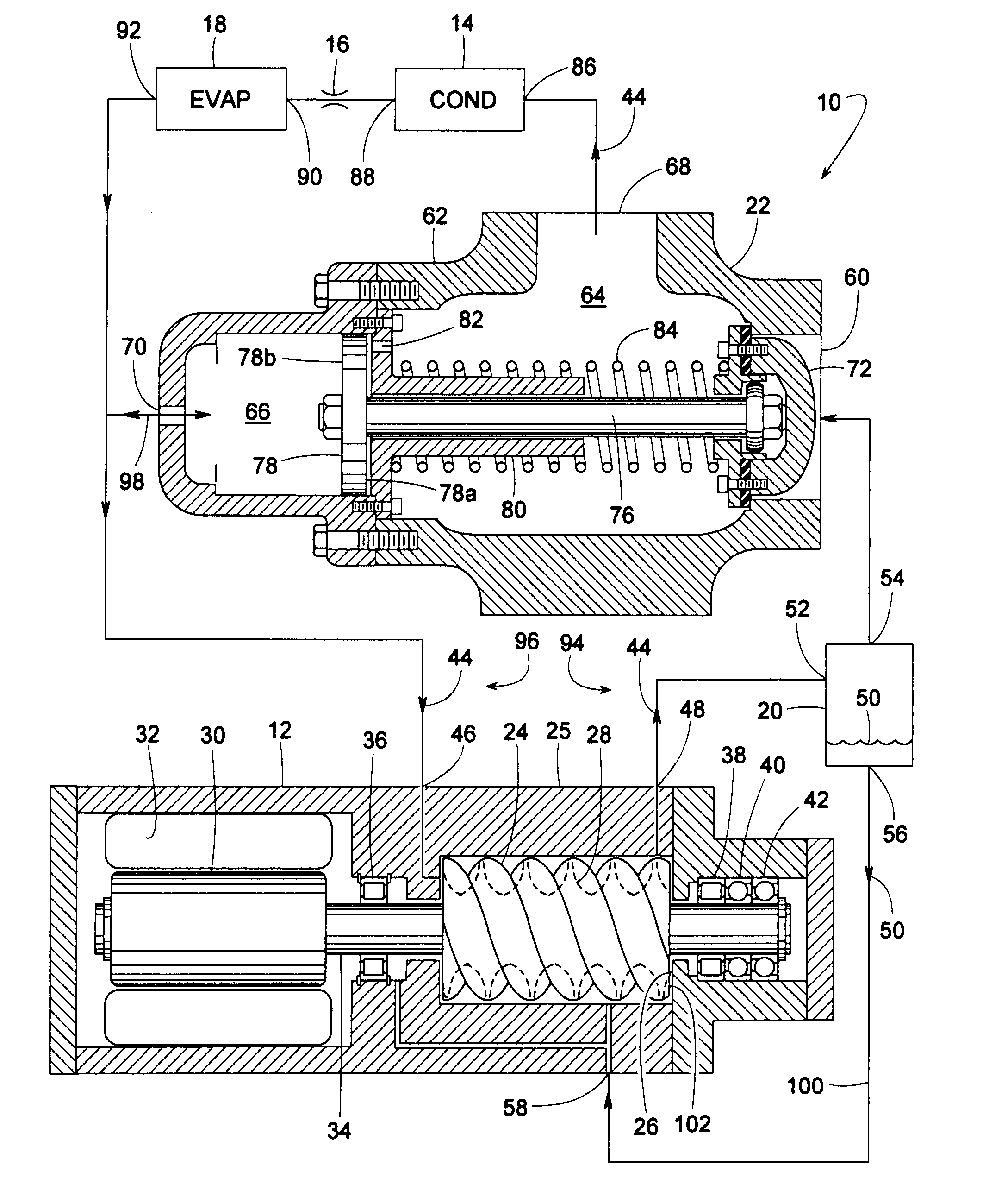
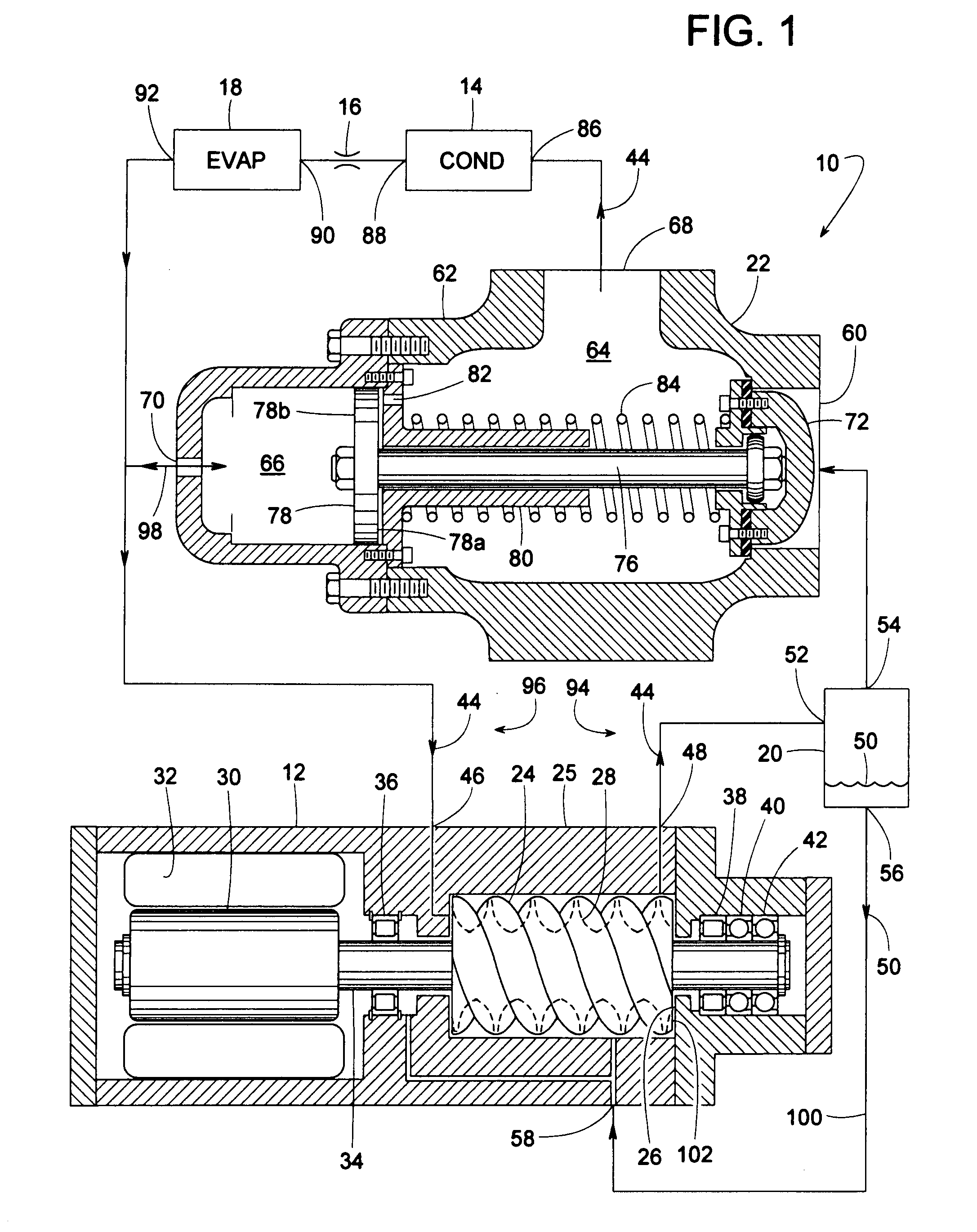
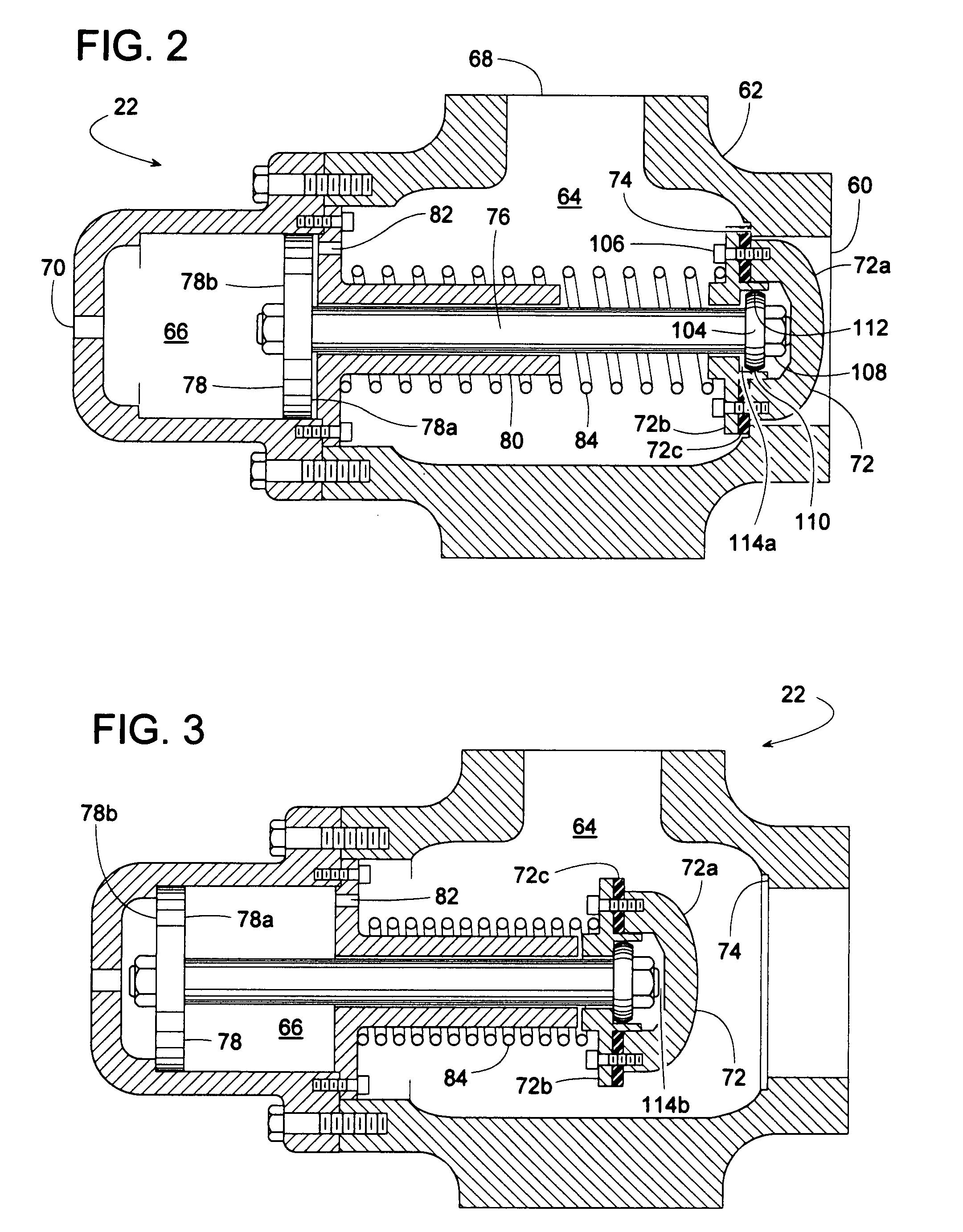
[0026]FIG. 1 schematically illustrates a refrigerant system 10 comprising a refrigerant compressor 12, a condenser 14, an expansion device 16, and an evaporator 18. System 10 also includes an oil separator 20 and a novel discharge valve 22. The various components are drawn out of scale to illustrate certain key features. Discharge valve 22 provides several benefits including, but not limited to, protecting evaporator 18 from freezing under certain conditions; ensuring proper lubrication of compressor 12 at startup; and preventing or minimizing axial rubbing between a screw rotor 24 and a bearing housing axial face 26 of compressor 12.

[0027]Although compressor 12 represents any type of compressor, compressor 12 is shown as being a screw compressor, as such a compressor can particularly benefit from the use of discharge valve 22. For the illustrated example, compressor 12 comprises a compressor housing 25 (which includes bearing housing axial face 26), two intermeshing screw compresso...


PUM


Abstract

A refrigerant system includes a compressor with a discharge valve that temporarily restricts the compressor's outflow at startup so that the discharge pressure can quickly rise to force lubricant back to the compressor. The discharge valve also helps prevent an axial face of a rotor of a screw compressor from rubbing against a bearing housing axial face of the compressor's housing. When the system turns off under certain low ambient air temperature conditions, the valve closes to help prevent the system's evaporator from freezing up. The discharge valve includes a novel arrangement of a piston, a valve stem extending from the piston, and a valve plug pivotally attached to the valve stem. The pivotal connection ensures a positive seal between the valve plug and a valve seat. A somewhat restricted fluid passageway between the valve's discharge chamber and piston chamber helps prevent the valve from chattering as the valve opens.

Description

BACKGROUND OF THE INVENTION[0001]1. Field of the Invention[0002]The subject invention generally pertains to refrigerant systems and more specifically to a compressor discharge valve that provides freeze and charge migration protection.[0003]2. Description of Related Art[0004]Various valves have been developed to ensure a refrigerant compressor has adequate lubrication at startup. Such valves typically restrict a compressor's initial discharge of refrigerant to quickly increase the discharge pressure so that the pressure is sufficient to force lubricant back to the compressor. Examples of such valves are disclosed in U.S. Pat. No. 5,134,856 (Pillis) and U.S. Pat. No. 5,170,640 (Heitmann).[0005]The Pillis valve includes a piston with a bleed hole (50) that allows high-pressure refrigerant to flow from a front side of the piston to a back side of the piston. Opening a solenoid valve (46) releases the high-pressure refrigerant at the back side of the piston so that the high-pressure ref...

Claims


Application Information

Patent Timeline
Patent Type & Authority Applications(United States)
IPC IPC(8): F25B1/00F16K31/44
CPCF16K31/1223F25B2600/0261F25B41/04F25B1/047F25B41/24
Inventor BEEKMAN, DENNIS M.JOHNSON, JAY H.LAKOWSKE, RODNEY L.SMITH, SEAN A.MOILANEN, JOHN R.
Owner TRANE INT INC
Learn More