Movement decoupling hydraulic driving three-degree-of-freedom spherical wrist
What is Al technical title?
Al technical title is built by PatSnap Al team. It summarizes the technical point description of the patent document.
A degree of freedom and motion technology, applied in the field of robotics, can solve the problems of limited attitude adjustment ability and precise positioning ability, large wrist weight, long wrist transmission chain, etc., to achieve strong attitude ability, compact structure and high power density. Effect
Active Publication Date: 2019-08-27
TAIYUAN UNIV OF TECH
View PDF5 Cites 11 Cited by
Summary
Abstract
Description
Claims
Application Information
AI Technical Summary
This helps you quickly interpret patents by identifying the three key elements:
Problems solved by technology
Method used
Benefits of technology
Problems solved by technology
[0006] The present invention aims at the problems existing in the above-mentioned traditional three-freedom wrist and the three-degree-of-freedom wrist based on motor transmission, gear transmission or belt transmission. Kinematic coupling and the heavy weight of the wrist itself lead to the limited flexibility, attitude adjustment ability and precise positioning ability of the end effector. It provides a small shape, compact structure, short transmission chain, strong attitude ability, high integration, High power density, motion decoupling, and hydraulically driven three-degree-of-freedom spherical wrist
Method used
Image
Click on the blue label to locate the original text in one second.
Reading with bidirectional positioning of images and text.
Examples
Embodiment Construction
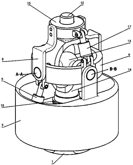
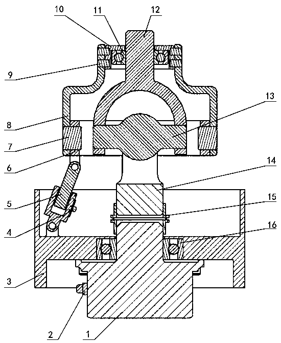
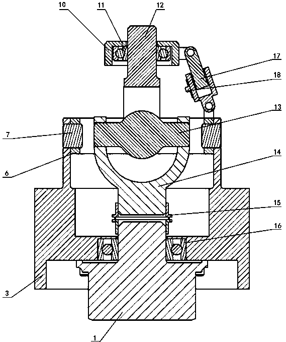
[0024] Attached below figure 1 ~ attached image 3To further illustrate the embodiment of the present invention, a hydraulically driven three-degree-of-freedom spherical wrist with motion decoupling is composed of an autorotation hydraulic motor 1, an angle sensor 2, a frame 3, a first displacement sensor 4, and a pitch hydraulic cylinder 5 , Pitch ring 6, first connecting screw 7, connecting rib 8, second connecting screw 9, side swing end cover 10, first bearing 11, second transmission shaft 12, universal joint 13, first transmission shaft 14. Coupling 15, second bearing 16, side swing hydraulic cylinder 17, and second displacement sensor 18, wherein the bottom of the frame 3 is provided with a cylindrical groove for placing the self-rotating hydraulic motor 1, and the middle is provided with a second bearing 16 The cylindrical groove and the round hole for the motor shaft to protrude. The top is provided with an auxiliary rib plate that is connected to the pitch ring 6 in ...
PUM
Abstract
The invention belongs to the technical field of robots, and particularly relates to a movement decoupling hydraulic driving three-degree-of-freedom spherical wrist. The problems that the flexibility,the posture adjustment capacity and the precision positioning capacity of an end effector are conducted due to the fact that a wrist is complex in structure, incompact, small in power intensity, low in integration level and high in self weight, a transmission chain is long, and movement coupling exists are solved. The movement decoupling hydraulic driving three-degree-of-freedom spherical wrist comprises a rotation hydraulic motor, an angle sensor, a machine frame, a displacement sensor, a pitching hydraulic oil cylinder, a pitching ring, a side-sway end cover, a bearing, a transmission shaft,a transmission shaft coupler and a side-sway hydraulic oil cylinder. The pitching axis, the side-sway axis and the rotation axis of the movement decoupling hydraulic driving three-degree-of-freedom spherical wrist cross at one point, uncoupling of three active input movements including pitching, side-sway and rotation can be achieved, thus, the posture of the wrist is easy and convenient to control, the control precision is high, the posture capacity is high, and the mechanical arm vibrating phenomenon caused by movement coupling generated during joint matching adjustment is avoided.
Description
technical field [0001] The invention belongs to the technical field of robots, and in particular relates to a hydraulically driven three-degree-of-freedom spherical wrist with motion decoupling. Background technique [0002] In today's rapidly developing society, robots are entering light industry, heavy industry, medical, military, aviation and other industries on a large scale, replacing humans to complete material transfer, assembly, classification, environmental survey, precise positioning and measurement of objects, light or micro processing And other operations, effectively reducing labor intensity, improving labor efficiency and prolonging working time, and even completing the working conditions that humans cannot handle due to various reasons. In response to this demand, many types of industrial robots have been developed. What these robots have in common is that they all need a flexible wrist mechanism to drive the end effector in order to effectively replace humans...
Claims
Application Information
Patent Timeline
Application Date:The date an application was filed.
Publication Date:The date a patent or application was officially published.
First Publication Date:The earliest publication date of a patent with the same application number.
Issue Date:Publication date of the patent grant document.
PCT Entry Date:The Entry date of PCT National Phase.
Estimated Expiry Date:The statutory expiry date of a patent right according to the Patent Law, and it is the longest term of protection that the patent right can achieve without the termination of the patent right due to other reasons(Term extension factor has been taken into account ).
Invalid Date:Actual expiry date is based on effective date or publication date of legal transaction data of invalid patent.