Method for determining the position of moving objects

a technology for moving objects and positions, applied in surveying and navigation, navigation instruments, instruments, etc., can solve the problems of inability to accurately determine the position or orientation, inability to meet the needs of infrastructure and access, etc., to achieve the effect of improving the localization speed, and reducing the computational effor

Active Publication Date: 2016-02-02
DEUTSCHES ZENTRUM FUER LUFT & RAUMFAHRT EV
View PDF13 Cites 2 Cited by
  • Summary
  • Abstract
  • Description
  • Claims
  • Application Information

AI Technical Summary

Benefits of technology

[0017]In particular due to the present calculation of a probability density function which is performed especially in dependence on distances between the position and the contour line, it is possible to significantly improve the determination of positions of objects also in closed rooms or in areas where no direct line-of-sight contact with a satellite is possible.
[0021]For a further improvement of the localization, in particular for an improvement of the speed of localization, the probability density functions for often occurring possible positions in an environment can be calculated in advance taking into account the environmental data and can be stored in a database. Thereby, the computational effort can be reduced significantly. In particular, this can be done for any possible position in a grid (e.g. 0.5 meters by 0.5 meters).

Problems solved by technology

Inside of buildings or when an object is in a blind area of the satellite, such as in narrow street canyons, strong interferences often occur that are due to the blocking of the direct signal path or due to multipath errors.
Substantial drawbacks of a combination with other radio systems are a possibly limited availability, the necessary infrastructure and a possibly restricted access.
In particular when a person is in a building for a longer period of time, the effect of sensor errors (drift) on the estimation of position or orientation may possibly grow infinitely.
It is an essential drawback of this method, however, that due to the drift, ever increasing errors in the orientation about the vertical axis occur which can be observed only in a limited manner by means of ZUPT.
As a consequence, primarily the estimation of the orientation of the person (i.e. the orientation about the vertical axis) becomes increasingly inaccurate.
It is another drawback of this method that also the estimated covered distance becomes inaccurate, though to a lesser degree.
Further, if this system is used exclusively, there is a drawback that only the relative positioning, especially with respect to a starting point, can be determined.
However, taking environmental data into account in this manner may lead to erroneous judgments in the determination of a position.
An essential drawback of the use of target points is that no suitable probability density function for possible orientations can be established therefrom, since the same depends on the selection of the target points and the observation range.

Method used


Image

  • Method for determining the position of moving objects
  • Method for determining the position of moving objects
  • Method for determining the position of moving objects

Examples


Embodiment Construction

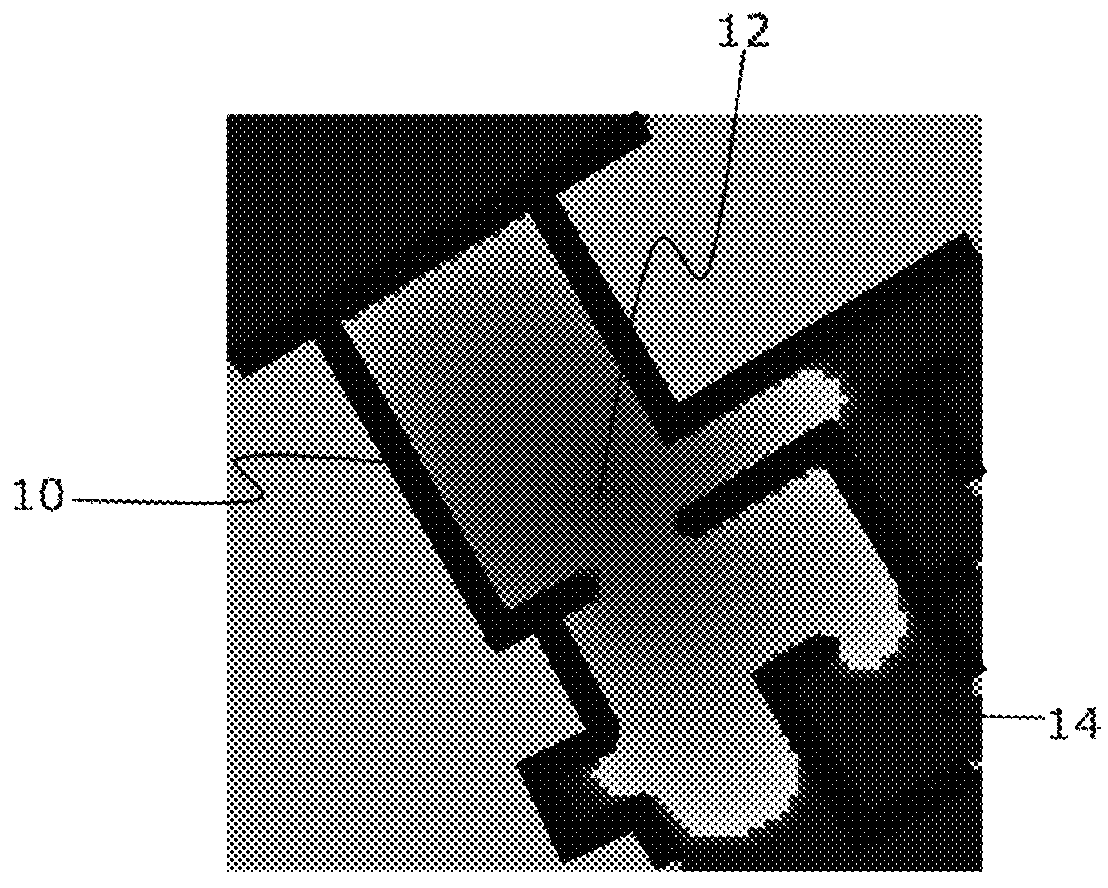
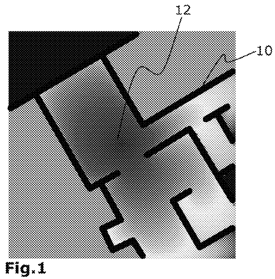
[0027]FIG. 1 shows a square detail of a building plan, the walls 10 in the building plan being illustrated as grey lines. The assumed current position 12 of an object, such as a person, is represented by the centre of the square shown in dark red. The highest value of the diffusion matrix is thus shown in dark red and decreases as the color changes to orange, yellow, green and blue. The diffusion matrix has been calculated by means of a diffusion filter. Preferably upon each recursion, the diffusion value at the assumed position (source of diffusion), i.e. at the centre of the square area in the example illustrated, is set to a predefined value, e.g. 1. At the walls 10, illustrated as grey lines in FIG. 1, the diffusion values are also set to a fixed value, in particular 0, during each step of the filtering, using a so-called layout matrix.

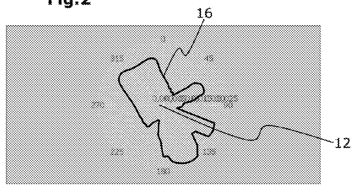
[0028]Based on a predetermined threshold value, a contour line 14 can then be determined. This is a closed line including those diffusion points ...


PUM


Abstract

Method for determining the position of moving objects, wherein the object has a sensor or an apparatus for determining odometry data, having the steps of: transmitting the odometry data to a calculation device, estimating the location and position of the object with the aid of the calculation device, creating a diffusion matrix on the basis of the estimated location and position taking into account environmental data, determining a contour line on the basis of the diffusion matrix, determining the distances between the position and the contour line for different orientations, in particular each orientation, and calculating a probability density function on the basis of the distances determined.

Description

BACKGROUND[0001]1. Field of the Disclosure[0002]The disclosure refers to a method for determining the position of moving objects such as persons or robots, for example. The method of the present disclosure is particularly suited for implementation in buildings or in regions or areas blocked to satellite navigation.[0003]2. Discussion of the Background Art[0004]The localization of objects, such as persons or goods, is often performed using satellite navigation, e.g. by GPS. Outside of buildings, this yields an acceptable level of accuracy even with pedestrians having modern devices. Inside of buildings or when an object is in a blind area of the satellite, such as in narrow street canyons, strong interferences often occur that are due to the blocking of the direct signal path or due to multipath errors.[0005]In order to improve the localization of objects also in such areas, it is known to use further radio systems such as WLAN mobile phone networks, UWB (Ultra-Wide Band) networks an...

Claims


Application Information

Patent Timeline
Patent Type & Authority Patents(United States)
IPC IPC(8): G01C21/00G01C21/16G01C21/20
CPCG01C21/00G01C21/005G01C21/16G01C21/206G01C21/188
Inventor KAISER, SUSANNAKHIDER, MOHAMMEDROBERTSON, PATRICK
Owner DEUTSCHES ZENTRUM FUER LUFT & RAUMFAHRT EV
Why Eureka
Try Eureka