Multiple voltage level driving for electrophoretic displays

a multi-voltage level, electrophoretic display technology, applied in static indicating devices, non-linear optics, instruments, etc., can solve the problems of reduced grayscale resolution, limited speed of display driver ics and display controllers, and current driving methods that restrict the number of grayscale outputs, etc., to achieve better grayscale resolution and better control

Active Publication Date: 2016-02-02
E INK CORPORATION
View PDF177 Cites 152 Cited by
  • Summary
  • Abstract
  • Description
  • Claims
  • Application Information

AI Technical Summary

Benefits of technology

[0009]The method can provide finer control over the driving waveforms and produce a better grayscale resolution.

Problems solved by technology

However, the driving methods currently available pose a restriction on the number of grayscale outputs.
This is due to the fact that display driver ICs and display controllers are limited in speed on the minimum pulse length that a waveform can have.
While current active matrix display architectures utilize ICs that can generate pulse lengths down to 8 msec leading to electrophoretic displays which have shortened response time, even below 150 msec, the grayscale resolution seems to diminish due to the incapability of the system to generate shorter pulse lengths.
In addition, the driving methods currently available are not sufficient for driving a color display device.

Method used


Image

  • Multiple voltage level driving for electrophoretic displays
  • Multiple voltage level driving for electrophoretic displays
  • Multiple voltage level driving for electrophoretic displays

Examples


example 1

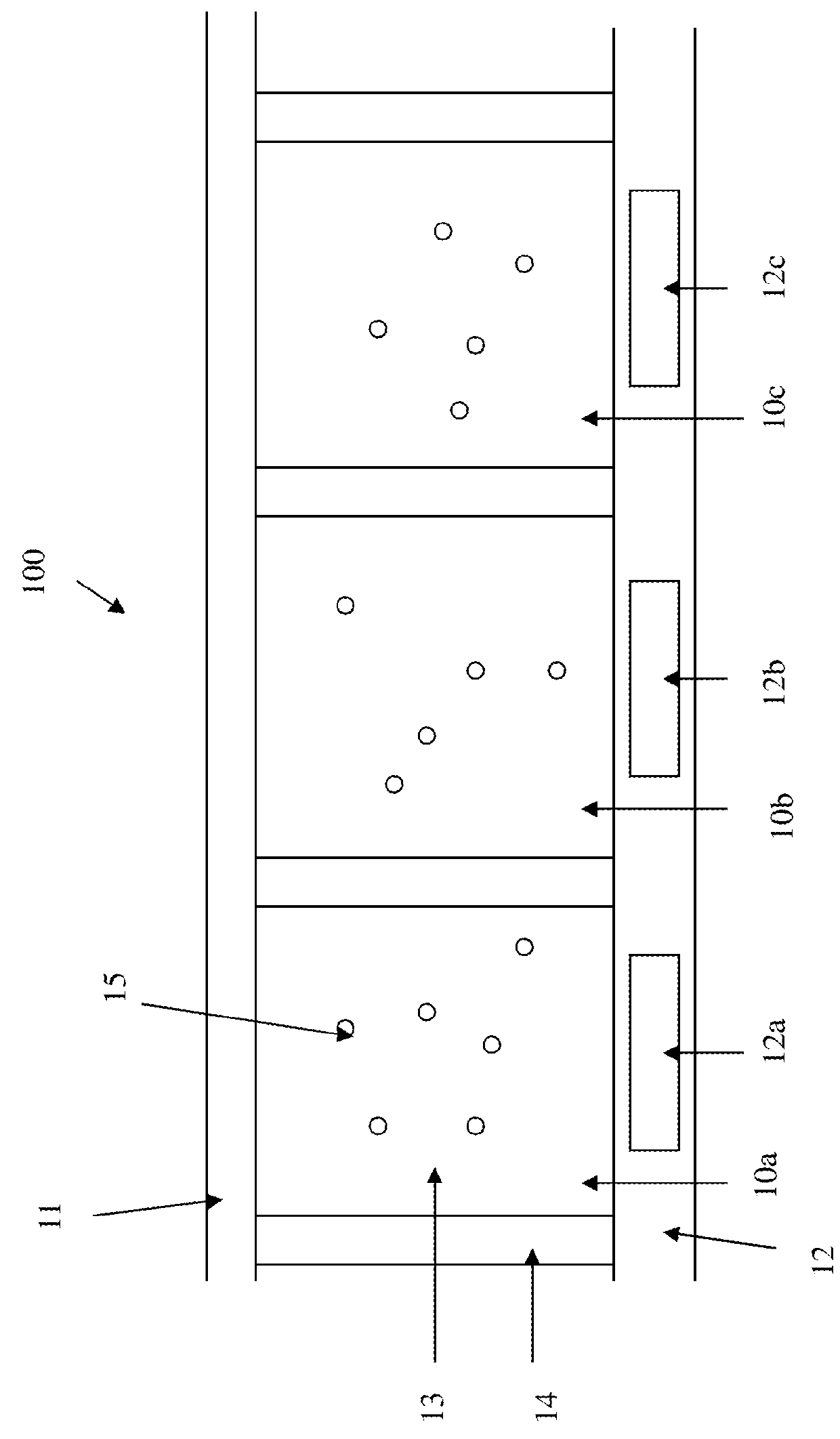
[0036]In FIG. 5, the white pigment particles (51) are negatively charged while the black pigment particles (52) are positively charged.

[0037]Because of the attraction between the positively charged black pigment particles (52) and the negatively charged white pigment particles (51), there is a threshold voltage of 5V. Due to the threshold voltage, the black particles (52) would not move to the viewing side if an applied voltage potential difference is 5V or lower.

[0038]The colored particles (53) carry the same charge polarity as the black particles which have the threshold voltage, but are slightly charged. The term “slightly charged” is intended to refer to the charge level of the particles being less than about 50%, preferably about 5% to about 30%, the charge intensity of the black or the white particles. As a result, the black particles (52) move faster than the colored particles (53), when an applied voltage potential is higher than the threshold voltage of the black particles ...

example 2

[0044]In FIG. 6, the white pigment particles (61) are negatively charged while the black pigment particles (62) are positively charged.

[0045]Because of the attraction between the positively charged black pigment particles (62) and the negatively charged white pigment particles (61), there is a threshold voltage of 5V. Due to the threshold voltage, the white particles (61) would not move to the viewing side if an applied voltage potential difference is 5V or lower.

[0046]The colored particles (63) carry the same charge polarity as the white particles which have the threshold voltage, but are slightly charged. The term “slightly charged” is as defined above.

[0047]In FIG. 6a, when a voltage potential difference of −15V is applied, the white particles (61) and the colored particles (63) move to be near or at the common electrode (64) and the black particles (62) move to be near or at the pixel electrode (65). As a result, the white color is seen at the viewing side. The colored particles...


PUM

PropertyMeasurementUnit
negative voltageaaaaaaaaaa
voltagesaaaaaaaaaa
voltagesaaaaaaaaaa

Abstract

This application is directed to driving methods for electrophoretic displays. The driving methods comprise applying different voltages selected from multiple voltage levels, to pixel electrodes and optionally also to the common electrodes. In one embodiment, the different voltages are selected from a group consisting of 0V, at least two levels of positive voltage and at least two levels of negative voltage. The driving method is also suitable for a color display device.

Description

[0001]This application is a continuation-in-part of U.S. application Ser. No. 12 / 695,817, filed Jan. 28, 2010; which claims the benefit of U.S. Provisional Application 61 / 148,746, filed Jan. 30, 2009. This application and is also a continuation-in-part of U.S. application Ser. No. 13 / 875,145, filed May 1, 2013; which is a continuation-in-part of U.S. application Ser. No. 13 / 633,788, filed Oct. 2, 2012. The above-identified applications are incorporated herein by reference in their entirety.TECHNICAL FIELD[0002]The present invention relates to methods comprising applying a voltage selected from multiple voltage levels to drive an electrophoretic display. The methods are also suitable for driving a color display device.BACKGROUND OF THE INVENTION[0003]An electrophoretic display (EPD) is a non-emissive device based on the electrophoresis phenomenon of charged pigment particles suspended in a solvent. The display usually comprises two plates with electrodes placed opposing each other. O...

Claims


Application Information

Patent Timeline
Patent Type & Authority Patents(United States)
IPC IPC(8): G09G3/34G09G3/32G02F1/167G09G3/20
CPCG09G3/3291G09G3/344G02F1/167G09G3/2003G09G3/2011G09G2310/06
Inventor LIN, CRAIGPHAM, TINCHAN, BRYANPERI, MANASAWANG, MINGLI, YUDU, HUIZHANG, XIAOJIA
Owner E INK CORPORATION
Why Eureka
Try Eureka