High power module cooling system

a technology for high-power modules and cooling systems, applied in cooling/ventilation/heating modifications, semiconductor devices, semiconductor/solid-state device details, etc., can solve the problems of system limitation, system bulkiness, and cos

Active Publication Date: 2016-02-02
TELEDYNE SCI & IMAGING
View PDF64 Cites 38 Cited by
  • Summary
  • Abstract
  • Description
  • Claims
  • Application Information

AI Technical Summary

Problems solved by technology

Power dissipation in electronic circuits remains an important design consideration and is becoming more important as performance for such circuits is becoming thermally limited.
Unfortunately, such systems are limited by the cooling capability (h) of the forced convection and by thermal resistance over the base plate and solder layer.
Such systems tend to be comparatively bulky and costly, however.
Use of DBC substrates to mount high power devices in combination with direct impingement liquid cooling has been found to improve thermal resistance over the base plate and solder layer, but the no-fin DBC solutions suffer from substantial loss in back-side cooling surface area and so thermal dissipation is greatly limited by the liquid impingement flow rate.
(See U.S. Pat. No. 7,190,581) Macro-scale fins may be attached DBC substrates, but such macro-scale fins block the liquid impingement path and are not made with commercially available DBC substrates thus adding cost to the total system solution.

Method used


Image

  • High power module cooling system
  • High power module cooling system
  • High power module cooling system

Examples


Embodiment Construction

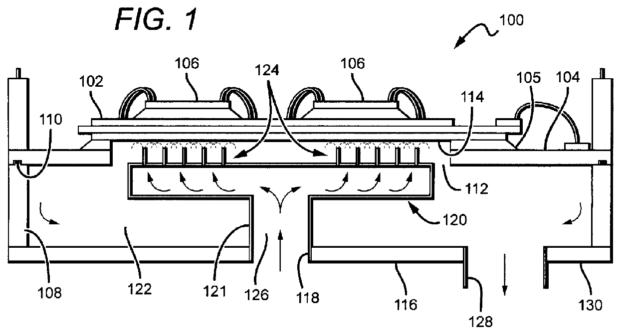
[0018]FIG. 1 illustrates one embodiment of a light-weight and compact high-power module cooling system 100 conformal to high power devices sitting on a substrate, with the high power devices and substrate collectively defining a “high power module.” The cooling system uses a phase-change material, preferably a liquid to enable a micro-jet / droplet based spray cooling, in a low thermal resistance packaging architecture. The phase-change material is preferably water, but may be a dielectric liquid, a water and ethalene glycol (WEG) mixture or consist of a microencapsulated phase change material such as tetradecane or octadecane. A micro-structured direct bonded copper (“DBC”) substrate 102 is thermally coupled to a module base plate 104, preferably a metal base plate formed of aluminum, aluminum silicon carbide or copper, for support and heat transfer. The DBC substrate 102 is thermally coupled to the module base plate 104 using a solder 105 such as SiIn or AuSn, or may be thermally co...


PUM


Abstract

A cooling apparatus includes a direct-bonded copper (“DBC”) substrate, the DBC substrate having a plurality of micro-structure tabs formed on a fluid impingement side of the DBC substrate, and a jet head in complementary opposition to the fluid impingement side. The jet head has a first plurality of micro-jets facing the fluid impingement side, each of the first plurality of micro-jets having a nozzle, and a second plurality of micro-jets facing the fluid impingement side so the jet head is configured to deliver a fluid to the plurality of micro-structure tabs through the first and second plurality of micro-jets.

Description

GOVERNMENTAL RIGHTS[0001]This invention was made with Government support under Contract No. 71305 (ONR) awarded by the Office of Naval Research. The Government has certain rights in this invention.BACKGROUND OF THE INVENTION[0002]1. Field of the Invention[0003]This invention relates to systems for cooling electronic devices, and particularly to systems for cooling high-power devices on a direct-bonded copper (DBC) substrate.[0004]2. Description of the Related Art[0005]Power dissipation in electronic circuits remains an important design consideration and is becoming more important as performance for such circuits is becoming thermally limited. For example, a power module having multiple high power devices sitting on a substrate needs to be cooled to prevent overheating and damage to the devices as well as to better-ensure long term reliability of the devices and their power connections. Many high power modules in commercial and military use are liquid cooled by forcing liquid flow th...

Claims


Application Information

Patent Timeline
Patent Type & Authority Patents(United States)
IPC IPC(8): H05K7/20H01L23/373H01L23/473
CPCH01L23/3735H01L23/4735H01L2224/32225H01L2224/48091H01L2224/48227H01L2224/73265H01L2924/19107H01L2924/00014H01L2924/00012H01L2924/00
Inventor BHUNIA, AVIJITMOFFATT, ALEX P.GARDNER, MARK R.CHEN, CHUNG-LUNG
Owner TELEDYNE SCI & IMAGING
Why Eureka
Try Eureka