
Methods and apparatuses for deuterium recovery

a technology of deuterium recovery and method, which is applied in the direction of sustainable manufacturing/processing, separation processes, and final product manufacturing, etc., can solve the problems of reducing the quality of integrated circuits, affecting the production efficiency of final products, and requiring a limited thermal budg

Active Publication Date: 2016-02-09
HPSP CO LTD
View PDF13 Cites 38 Cited by
  • Summary
  • Abstract
  • Description
  • Claims
  • Application Information

AI Technical Summary

Benefits of technology

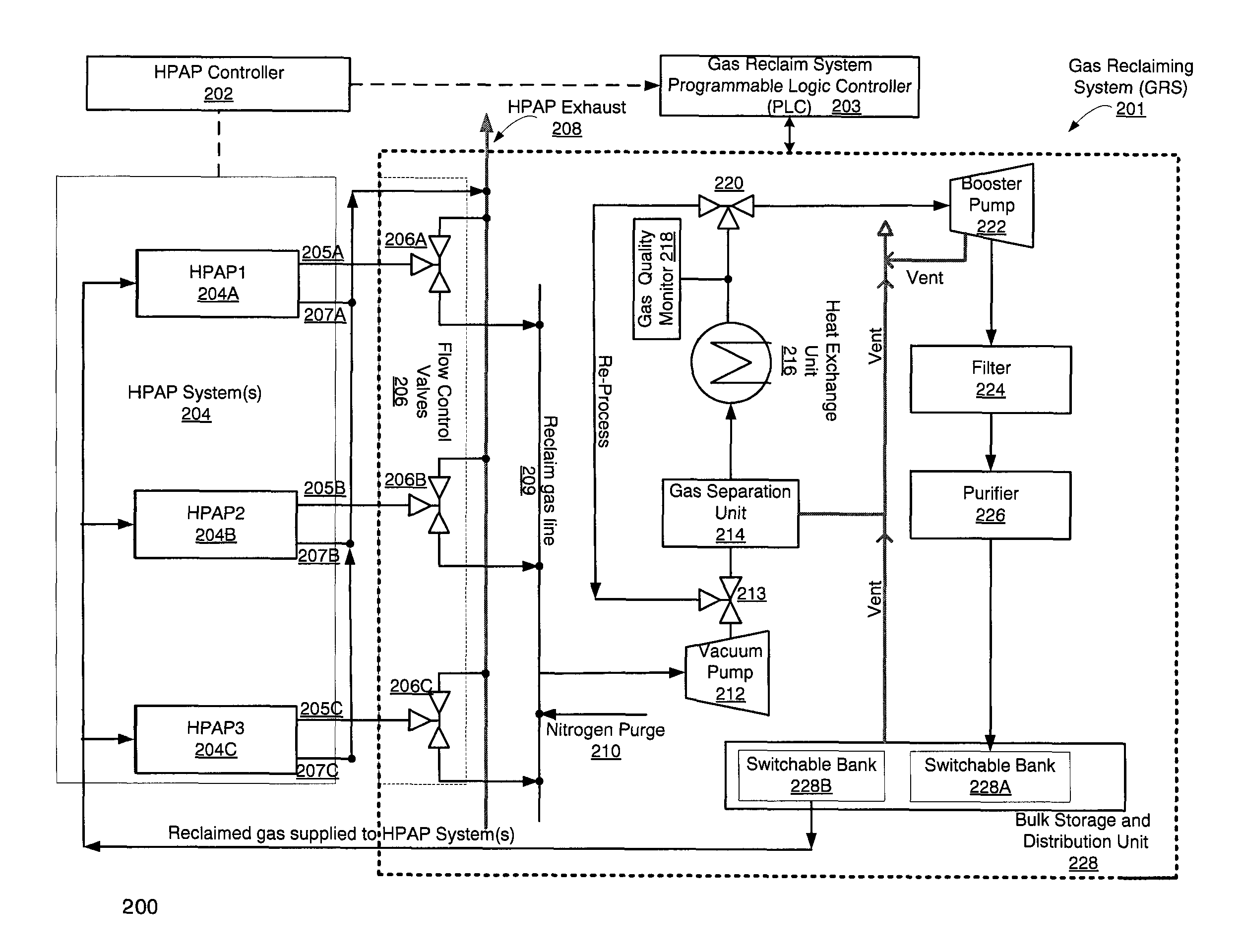
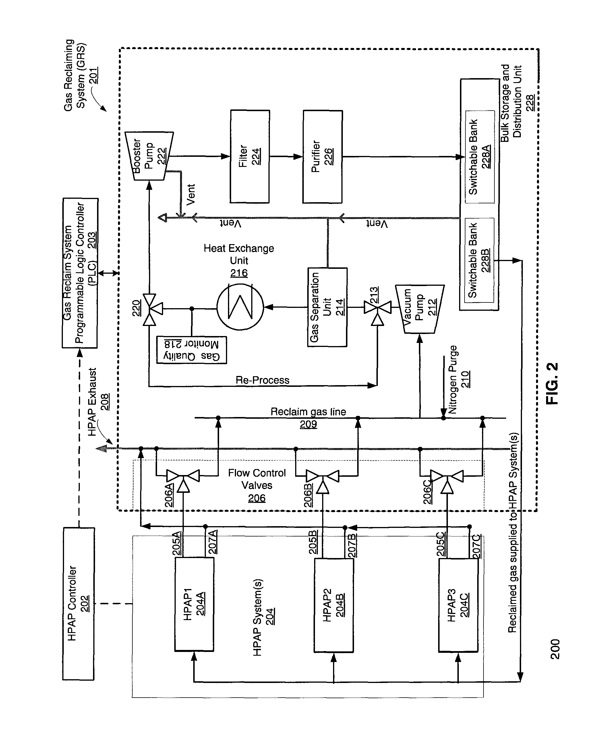
The patent describes a system for reclaiming and purifying the exhaust gas used in a high pressure annealing process for semiconductor manufacturing. The system includes a gas reclaiming system and a valve switchably coupling the inner chamber of the HPAP system to either an atmospheric exhaust or the gas reclaiming system. The gas reclaiming system purges the system with a second gas, separates the annealing gas from other gases, and pressurizes it for further use in the HPAP process. The system also includes a data processing system to control the valve and a low pressure gas capture system to retrieve the annealing gas from the inner chamber. The technical effect of the patent is to provide a more efficient and effective method for reclaiming and purifying the exhaust gas used in semiconductor manufacturing processes.

Problems solved by technology

It should be noted that exposure of semiconductor wafers, or more precisely integrated circuits, to excessive heat generally degrades the quality of the integrated circuits, in an irreversible and cumulative way.
As the technology and device structure approaches the nanometer scale, the limited thermal budget requirement demands higher concentration of the processing gas.
However, as the device scale reaches 28 nm or below, the limited thermal budget after first metallization requires annealing temperatures at or below 400° C., thus potentially diminishing the hydrogen annealing benefit on semiconductor device performance.
The outer shell chamber is pressurized by gas typically different from the processing gas, which may be highly reactive, flammable, or otherwise dangerous.
This could be a source of safety problem.
No system exists that could safely extract the used precious annealing gas (e.g., deuterium) from the exhaust of the annealing process for reuse.

Method used


Image

  • Methods and apparatuses for deuterium recovery
  • Methods and apparatuses for deuterium recovery
  • Methods and apparatuses for deuterium recovery

Examples


Embodiment Construction

[0037]The present invention will now be described more fully hereinafter with reference to the accompanying drawings, in which various exemplary embodiments of the invention are shown. This invention may, however, be embodied in many different forms and should not be construed as limited to the embodiments set forth herein; rather, these embodiments are provided so that this disclosure will be thorough and complete, and will fully convey the scope of the invention to those skilled in the art. Likewise, for purposes of explanation, numerous specific details are set forth in the following description in order to provide a thorough understanding of the present invention. It will be evident, however, to one skilled in the art that the present invention may be practiced without these specific details. Reference in the specification to “one embodiment” or “an embodiment” or “another embodiment” means that a particular feature, structure, or characteristic described in conjunction with the...


PUM

PropertyMeasurementUnit
temperatureaaaaaaaaaa
temperaturesaaaaaaaaaa
pressuresaaaaaaaaaa

Abstract

Novel methods, systems, and apparatuses for reclaiming annealing gases from a high pressure annealing processing system are disclosed. According to an embodiment, the exhaust gasses from the high pressure annealing processing system are directed into a gas reclaiming system only when a precious gas, e.g., deuterium is used. The annealing gas is the separated from other gasses used in the high pressure annealing processing system and is then pressurized, filtered, and purified prior to transferring the gas to a bulk storage distribution unit. In one embodiment, the reclaimed gas is then again provided to the high pressure annealing processing system to anneal the wafers.

Description

BACKGROUND OF THE INVENTION[0001]1. Field of the Invention[0002]The present invention generally relates to semiconductor manufacturing process. More particularly, the present invention pertains to methods and apparatuses which use precious gases, like deuterium, during a high pressure annealing process of semiconductor manufacturing.[0003]2. Description of the Related Art[0004]During the semiconductor manufacturing process, various different thermal treatments are performed on a semiconductor wafer, for example, during or following oxidation, nitridation, silicidation, ion implantation, and chemical vapor deposition processes, to create the integrated circuits on the semiconductor wafer.[0005]Key determining factors for effective fabrication of integrated circuits not only include the process temperature, but also the processing time and the concentration of a particular gas or a mixture of gases used for a particular application or treatment. These three factors are generally consi...

Claims


Application Information

Patent Timeline
Patent Type & Authority Patents(United States)
IPC IPC(8): H01L21/324B01D53/02B03C3/36C01B4/00B01D46/44H01L21/67B01D46/00H01L21/477
CPCH01L21/67098B01D46/0019B01D46/442B01D53/02B03C3/36C01B4/00B01D2253/116H01L21/67017H01L21/67109Y02C20/30Y02P70/50B01D46/0027B01D46/0036B01D53/002B01D53/32C23C16/4402C23C16/4408C23C16/4412H01L21/67103H05B1/0202H05B1/0233
Inventor RIVERA, MANUELWU, BIAO
Owner HPSP CO LTD
Learn More