Touch input device and system thereof

a technology of input device and capacitive touchscreen, which is applied in the direction of instruments, computing, electric digital data processing, etc., can solve the problems of wasting the active stylus pen and the tablet computer more power, affecting the use time of both, and unable to achieve the following requirements

Active Publication Date: 2016-02-16
SILICON INTEGRATED SYSTEMS
View PDF5 Cites 6 Cited by
  • Summary
  • Abstract
  • Description
  • Claims
  • Application Information

AI Technical Summary

Benefits of technology

[0006]Accordingly, an objective of the present invention is to provide a touch input device, which is capable of emitting a pulse width modulation (PWM) signal to influence an original touchscreen driving signal through a pen tip, so that a capacitive touchscreen can identify the force that exerts to the pen based on the influenced driving signal.
[0007]Another objective of the present invention is to provide a touch input system, which is capable of emitting the PWM signal to influence an original touchscreen driving signal through a pen tip, so that the capacitive touchscreen can determine the line thicknesses displayed on the capacitive touchscreen based on the influenced driving signal.
[0018]In comparison with the prior art, the present invention employs a duty cycle of the PWM signal to control the voltage difference, thereby affecting the strength of the driving signal received by the touch controller, so as to achieve the touch effect of pressure-sensitive feedback.

Problems solved by technology

However, although the touch input by the fingers is convenient, it is obviously difficult to achieve the following requirements: depicting lines with various thicknesses on the touchscreen, or touch recognition for fine locations by using the fingers.
Although it can achieve a more accurate input than the finger input, the capacitive stylus pen also can not depict the lines with the various thicknesses on the screen corresponding to force that exerts to the pen, the shortcoming of the usage still existing.
However, the establishment of the wireless communication will waste the active stylus pen and the tablet computer more power, and it is a disadvantage to the using time for both.

Method used


Image

  • Touch input device and system thereof
  • Touch input device and system thereof
  • Touch input device and system thereof

Examples


Embodiment Construction

[0027]The present invention will now be described in detail with reference to a few preferred embodiments thereof as illustrated in the accompanying drawings. The same reference numerals refer to the same parts or like parts throughout the various figures.

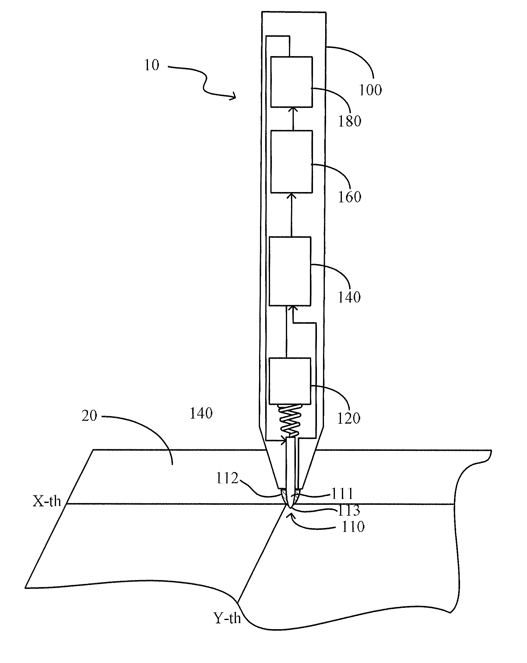
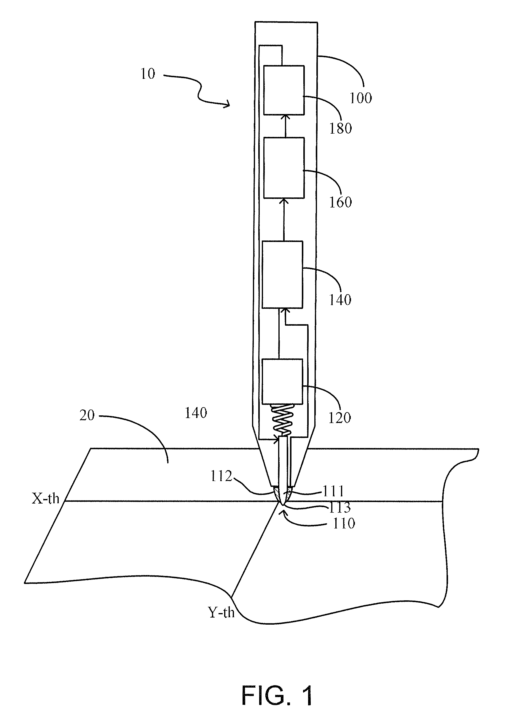
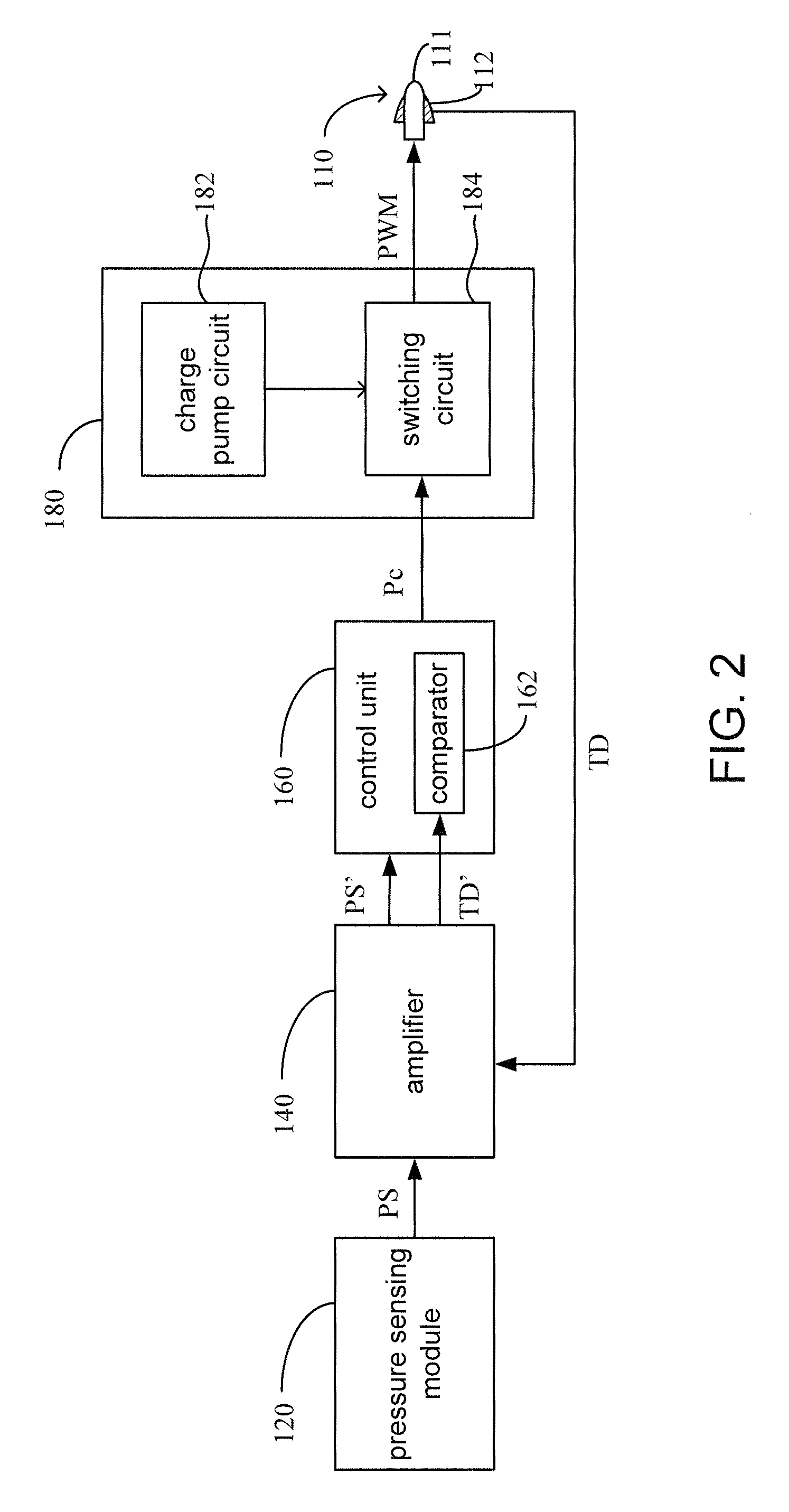
[0028]Referring to FIG. 1 and FIG. 2, FIG. 1 is a perspective view schematically illustrating a touch input device according to a preferred embodiment of the present invention; FIG. 2 is a block diagram illustrating a touch input device according the preferred embodiment of the present invention. The touch input device 10 of the embodiment is utilized to perform an input on a capacitive touchscreen 20. Preferably, the touch input device 10 can be an active stylus pen 100, which equips with a battery (not shown) to supply electric power as desired. As shown in FIG. 1, the touch input device 10 includes a pen tip 110, a pressure sensing module 120, an amplifier 140, a control unit 160 and a pulse width modulation (PWM) generator 180....


PUM


Abstract

A touch input device provided in the present invention includes a pen tip, a pressure sensing module, a control unit and a PWM generator. The pen tip is utilized to touch a capacitive touchscreen and conduct a touchscreen driving signal. The pressure sensing module is utilized to generate a pressure sensing signal which corresponds to a pressure of the pen tip on the capacitive touchscreen. The control unit is utilized to receive the touchscreen driving signal and the pressure sensing signal, and then to generate a PWM control signal according to the pressure sensing signal. Further, a pulse width of the PWM control signal is proportional to the pressure. The PWM generator is utilized to provide a PWM signal to the pen tip according to the PWM control signal. A touch input system is further provided in the present invention.

Description

TECHNICAL FIELD OF THE INVENTION[0001]The present invention relates to a touch input device and a system thereof, and especially to a touch input device and a system for a capacitive touchscreen.BACKGROUND OF THE INVENTION[0002]Touch technology can be divided into the following types: resistive, capacitive, surface acoustic wave, optics, etc according to the sensing principles thereof. With the convenience of usage and the demand for multi-touch, the capacitive touch technology inputting by fingers has become the mainstream of current electronic products.[0003]A structure of a capacitive touch panel is a substrate on which transparent electrode patterns are coated. When a finger is close to or touches the touch panel, coupling capacitance is formed between the finger and the transparent electrode patterns because the finger is a conductor and has equivalent capacitance. Meanwhile, the capacitance of the electrode pattern positioned at a touch point on the touch panel will change, th...

Claims


Application Information

Patent Timeline
Patent Type & Authority Patents(United States)
IPC IPC(8): G06F3/044G06F3/0354
CPCG06F3/044G06F3/03545G06F3/0414G06F3/04162G06F3/0442
Inventor YU, MU-TSANYEH, YING-JYH
Owner SILICON INTEGRATED SYSTEMS
Why Eureka
Try Eureka