
Microbicidal filter and filtration cartridge incorporating such a filter

a technology of microbicidal filters and filtration cartridges, which is applied in the direction of filter regeneration, dispersed particle filtration, and liquid separation agents, can solve the problems of health risks of people carrying out this work, and achieve the effect of stable construction over time and less cos

Inactive Publication Date: 2016-02-23
LIND DU PONANT
View PDF10 Cites 9 Cited by
  • Summary
  • Abstract
  • Description
  • Claims
  • Application Information

AI Technical Summary

Benefits of technology

[0004]The aim of the invention is therefore to propose a microbicidal filter and a cartridge incorporating such a filter that is inoffensive during replacement thereof and treatment thereof in the course of time as waste, and which is of a construction stable over time and at less cost.
[0009]The efficacy of the action of the impregnated layer is increased because it is juxtaposed against a HEPA filter, the bactericidal and / or fungicidal agent being able also to diffuse as far as the HEPA filter in the gap that separates them in order to inhibit or kill the living particles retained on the HEPA filter. Moreover, the HEPA filter is interposed, at least locally, between the two filtration layers so that it does not deform in use and procures for the filter a change in its performances over time that is predictable.
[0011]The service life of the microbicidal filter is increased by preventing the collapse of the HEPA filter. Moreover, the change in the fouling of the filter remains relatively low.
[0015]The polypropylene fibres are arranged in the form of a three-dimensional medium and in this way have remarkable filtering capacity. The ion / silver particles have a destructive effect on the living particles.

Problems solved by technology

The living particles trapped by the HEPA filter do however remain living and may contaminate the air, in particular during the filter replacement operation, so that the person carrying out this work is exposed to a health risk.

Method used


Image

  • Microbicidal filter and filtration cartridge incorporating such a filter
  • Microbicidal filter and filtration cartridge incorporating such a filter
  • Microbicidal filter and filtration cartridge incorporating such a filter

Examples


Embodiment Construction

)

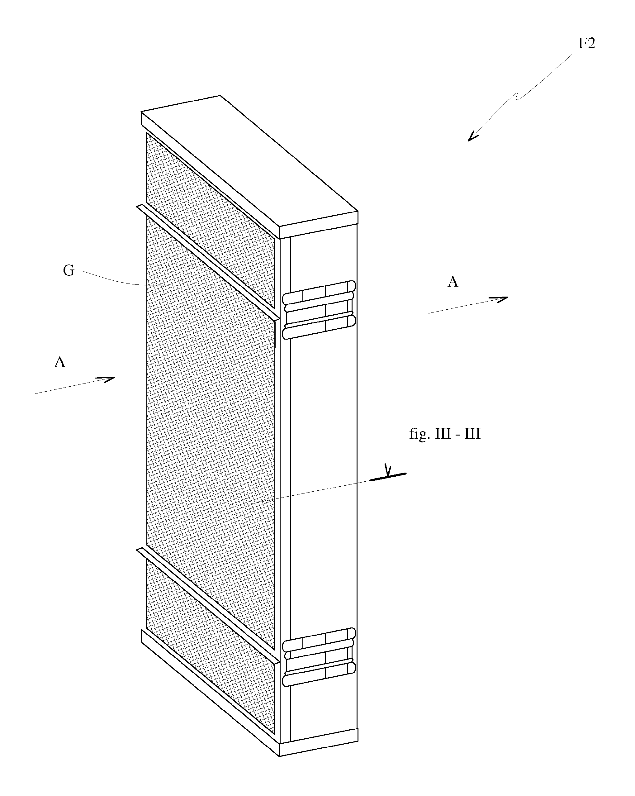
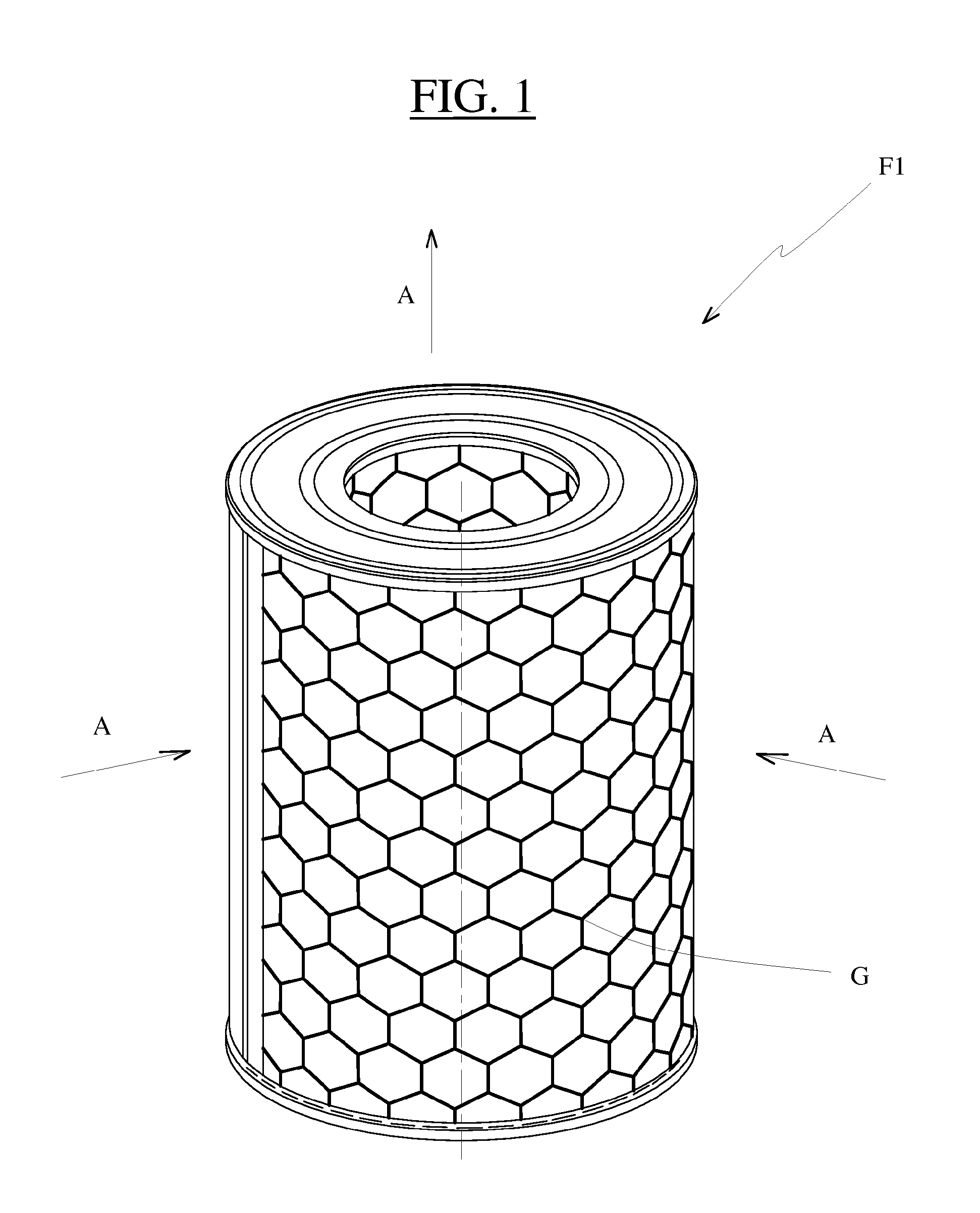
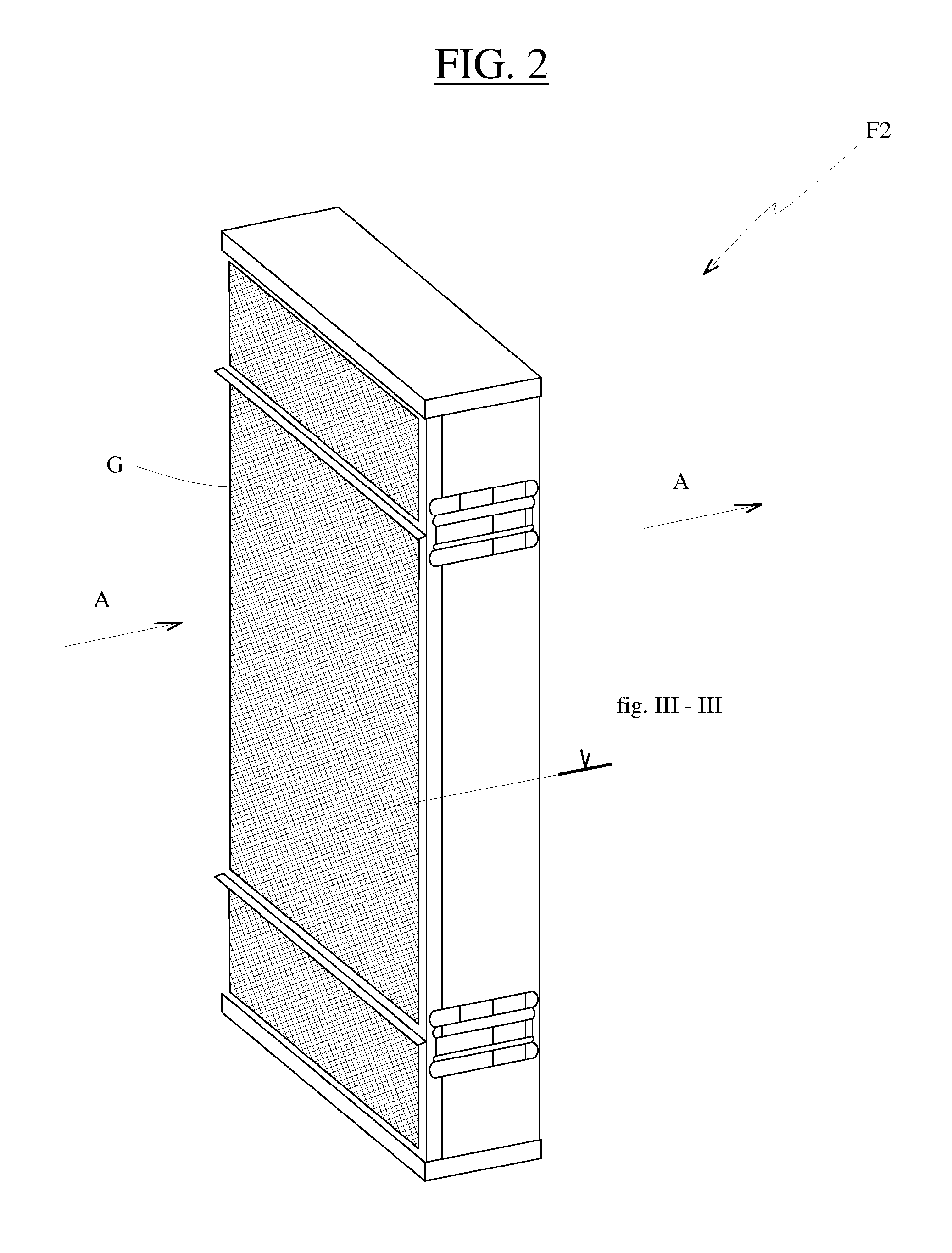
[0023]The filtration cartridge F presented in FIGS. 1 and 2 is intended to be placed in an air treatment circuit for purifying if from the dust in suspension that it contains but also retaining pathogenic particles of smaller sizes, such as bacteria, germs, microbes and viruses. It is also effective for retaining and annihilating volatile chemical molecules.

[0024]Its application covers the field of filtration in aircraft cabins, in vehicles and in medical rooms, the field of controlled mechanical ventilation in dwellings, and in general terms all sectors of activity requiring air free from microbial or chemical pollution.

[0025]It comprises, in FIG. 1 and under the reference F1, a cylindrical frame and, in FIG. 2 and under the reference F2, a parallel epipedal frame, so that it can be connected in accordance with current standard principles.

[0026]In the first connection configuration, the air flow, represented by the arrow A, passes through it at the periphery in order to emerge thr...


PUM

PropertyMeasurementUnit
sizeaaaaaaaaaa
sizeaaaaaaaaaa
sizeaaaaaaaaaa

Abstract

A microbicidal filter for treating air, includes, in the allocated direction of flow of the air stream capable of passing therethrough, a filtration layer and a HEPA filter. The filtration layer contains a bactericidal and / or fungicidal agent, and the HEPA filter is pleated while being applied against a second pleated filtration layer that is arranged downstream, so as to prevent the mutual contacting of its pleats. The combination of the action of the impregnated layer and of the HEPA filter inhibits or kills by contact all the living particles that penetrate into the microbicidal filter. The HEPA filter is held in stable application in the pleated shape thereof against the second filtration layer, so that filtering performance deteriorates only gradually.

Description

BACKGROUND[0001]The present invention relates to a microbicidal filter for treating air and a filtration cartridge comprising such a filter.[0002]A filter for clean rooms and hospitals is known from a reading of the document U.S. Pat. No. B-4,323,374. It is composed, in a preferential configuration, of a HEPA filter conformed in a zigzag, downstream of which a filtration layer is placed, fabricated from polypropylene fibres with an electrostatic property. The upstream HEPA layer retains the particles and microbes with a size of less than 0.3 micrometers. The downstream layer retains a large quantity of particles with a size of less than 0.111 micrometers. Separators are placed between the pleats of a pleated element to separate its walls. The advantages proposed are high efficiency and low fouling.[0003]The living particles trapped by the HEPA filter do however remain living and may contaminate the air, in particular during the filter replacement operation, so that the person carryi...

Claims


Application Information

Patent Timeline
Patent Type & Authority Patents(United States)
IPC IPC(8): B01D46/00B01D46/52
CPCB01D46/0028B01D46/0023B01D46/523B01D2275/10B01D46/62
Inventor KADDOUR, STEPHANE
Owner LIND DU PONANT
Learn More