
Method of in-situ pipeline replacement

Active Publication Date: 2016-03-01
NIPPES JOSEPH TIMOTHY
View PDF11 Cites 1 Cited by
  • Summary
  • Abstract
  • Description
  • Claims
  • Application Information

AI Technical Summary

Benefits of technology

The patent is about a method for replacing an old pipeline with a new deformed pipeline, which allows for easier installation and replacement of appurtenances like valves and service connections. The new pipeline is made of a polymer material and is expanded and connected to the old pipeline using standard techniques. The method also includes replacing appurtenances with standard fittings and utilizing transition or adapters to connect the new pipeline to standard fittings. The new pipeline is then tested, filled, and disinfected for service. Overall, the technical effect of the patent is facilitating the replacement of old pipelines with new pipelines that are easier to install and replace.

Problems solved by technology

Many cast iron pipelines supplying our drinking water and natural gas and carrying away our sewerage are aging, corroding, and generally wearing out.
In urban areas where space is tight and buried infrastructure is very dense, buried pipelines are particularly expensive to replace.
Treatment plants are the most expensive part of the sanitary sewer disposal process and reducing ground water infiltration saves capacity and money.
The rehabilitation of pressurized pipelines carrying water, sewerage, natural gas, or other materials is more complicated.
Finally, pressure pipes have appurtenances attached to them like valves, tees, wyes, elbows, bends, and others which further complicate rehabilitation and replacement.
Additionally, soil surrounding an exterior pipe wall may have a chemical composition which causes corrosion, further deteriorating the pipe.
This process does not add any structural strength to the existing pipe; it only improves water quality and flow.
Pipe bursting is well established but expensive as is any version of digging and replacing.
Slip lining is simple and straight forward but usually reduces capacity to an unacceptable level because of the reduced diameter of the new pipe.
CIPP for water or other pressure lines is expensive, appurtenances are difficult to attach, it may need to rely on the existing pipeline for structural integrity, and it requires a long lead time to install properly.
If the liner is too large in diameter, it will create a fold which will weaken the liner.
If it is too long, it will be difficult to install.
If it is too small in diameter, it may be weakened by not being in contact with the cast iron pipe walls.
If it is too short, it will be unusable because it would be impossible to finish the ends.
The major expense of this process comes before and after the application of the cement mortar.
It should be noted the difficulty factor of using a 6-inch HDPE pipe to slip line eight inch cast iron pipe is extremely high and would seldom, if ever, be attempted in real field conditions.

Method used


Image

  • Method of in-situ pipeline replacement
  • Method of in-situ pipeline replacement

Examples


Embodiment Construction

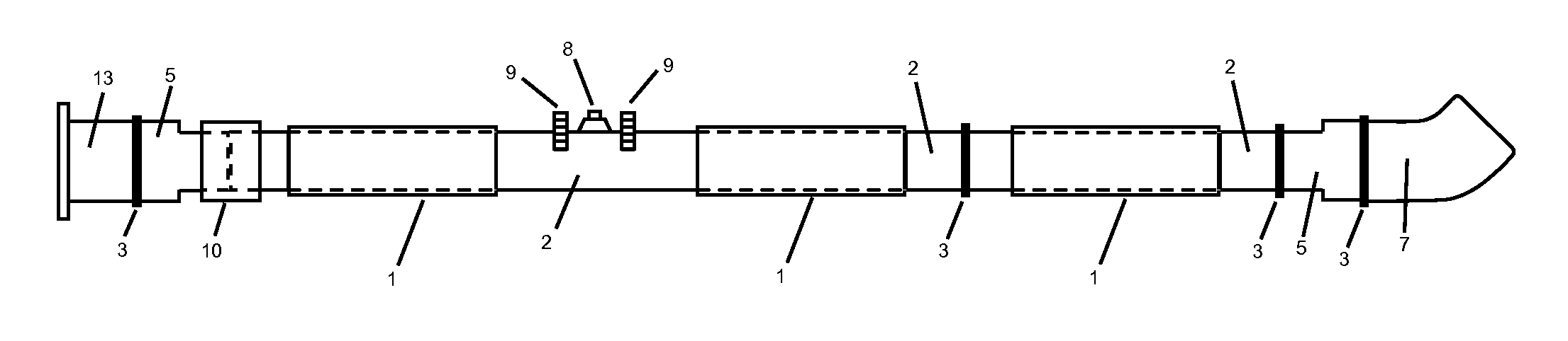
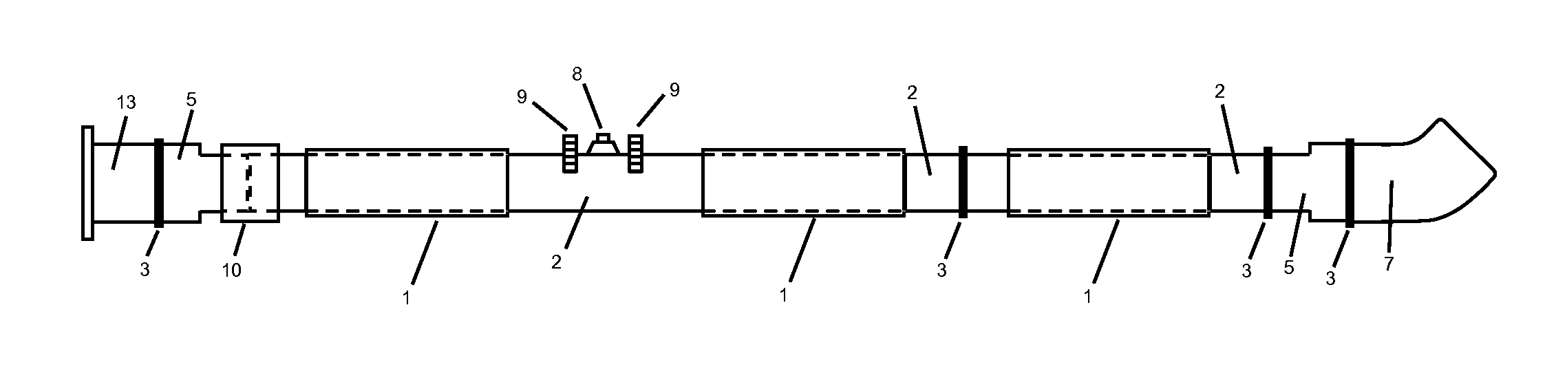
[0045]Referring now to the invention in more detail, there is shown an existing pipeline 1 and it is the pipeline to be replaced. Existing pipeline 1 is only used as a void in which to install new heat-fusible polymer pipeline 2 and is in no way relied upon by the new pipeline created per the method of this invention. New heat-fusible polymer pipeline 2 is installed inside existing pipeline 1. New heat-fusible polymer pipeline 2 is installed in a deformed configuration, often u-shaped and about half its expanded diameter, and expanded in situ to use up to 100 percent of the interior diameter of existing pipeline 1. Sections of new heat-fusible polymer pipeline 2 are joined to each other as needed with butt fusion 3. Joining of sections of new heat-fusible polymer pipeline 2 could be done prior to installation into existing pipeline 1 or after installation or after both installation and expansion. Butt fusion after installation requires a small break in existing pipeline 1 in which t...


PUM


Abstract

A method of in-situ pipeline replacement in which valves, fittings, and other obstructions are removed from an existing pipeline, a heat-fusible polymer pipeline having an initially deformed configuration less than the existing pipeline diameter is inserted into the remaining portions of the existing pipeline and reformed to substantially conform to the inside diameter of the existing pipeline, heat-fusible fittings are provided to replace removed portions of the existing pipeline and heat-fused to the polymer liner, and transition fittings provided to operably connect the replacement pipeline to those portions of the existing pipeline not within the replacement scope. The completed replacement polymer pipeline creates an operable wetted pressure boundary within the bounds of the replaced existing pipeline.

Description

CROSS-REFERENCE TO RELATED APPLICATIONS[0001]This application claims the benefit of provisional patent application Ser. No. 61 / 748,162 filed 2013 Jan. 2 by the present inventor.STATEMENT REGARDING FEDERALLY SPONSORED RESEARCH OR DEVELOPMENT[0002]Not ApplicableREFERENCE TO SEQUENCE LISTING, A TABLE, OR A COMPUTER PROGRAM LISTING COMPACT DISK APPENDIX[0003]Not ApplicableBACKGROUND OF THE INVENTION[0004]1. Field of the Invention[0005]The present invention is in the technical field of heavy construction related to the installation, repair, and replacement of pipelines. Particularly, the present invention is in the technical field of in-situ replacement methods of existing pressure pipelines such as, but not limited to, drinking water, natural gas, and sewerage. “In situ” is a Latin phrase meaning “in position,” and in this case means the old pipeline is replaced without complete removal or excavation.[0006]2. Description of the Prior Art[0007]Many cast iron pipelines supplying our drink...

Claims


Application Information

Patent Timeline
IPC IPC(8): F16L41/00F16L1/032
CPCF16L1/032E03F3/06F16L55/1604F16L55/1654F16L55/1657E03B7/006E03F2003/065E03B1/00F16L1/038F16L55/1608
Inventor NIPPES, JOSEPH, TIMOTHY
Owner NIPPES JOSEPH TIMOTHY
Features
  • Generate Ideas
  • Intellectual Property
  • Life Sciences
  • Materials
  • Tech Scout
  • Unparalleled Data Quality
  • Higher Quality Content
  • 60% Fewer Hallucinations
Learn More