Light emitting diode output power control

a technology output power, applied in the field of output power control of light emitting diodes, can solve problems such as the cracking of some parts of the distribution, and achieve the effect of reducing the degree of variation and reducing the amount of optical power

Active Publication Date: 2016-03-01
EXCELITAS TECH PHILIPPINES
View PDF21 Cites 0 Cited by
  • Summary
  • Abstract
  • Description
  • Claims
  • Application Information

AI Technical Summary

Benefits of technology

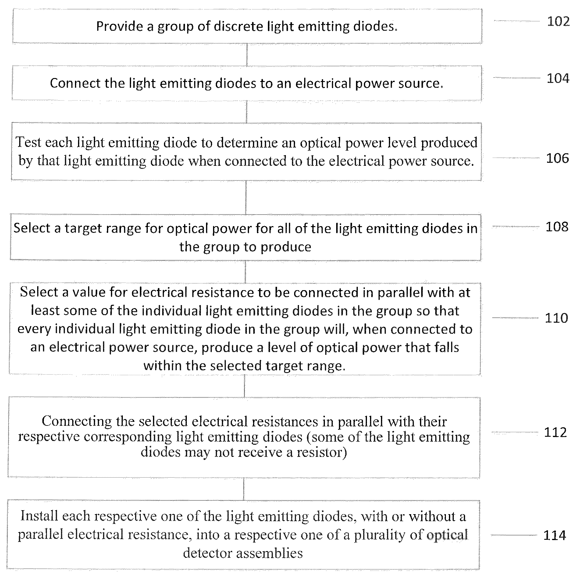
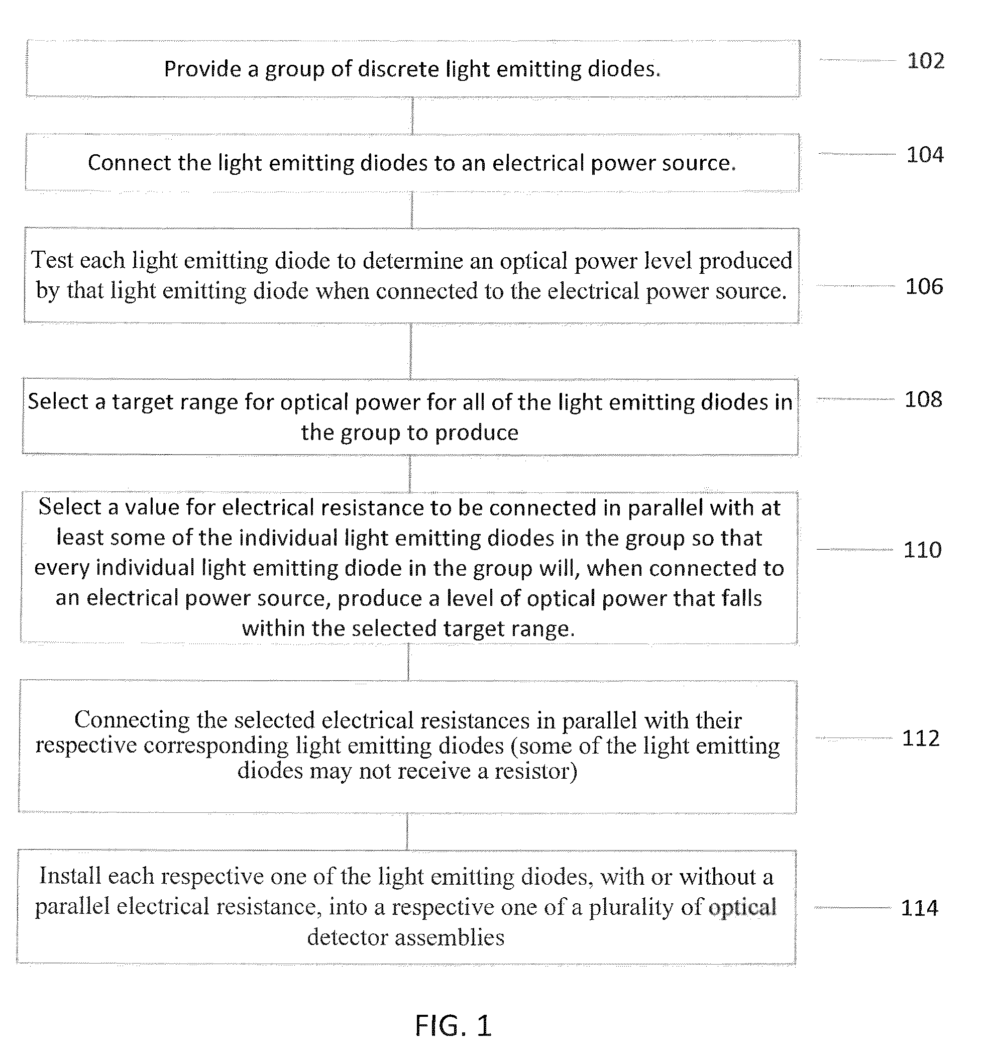
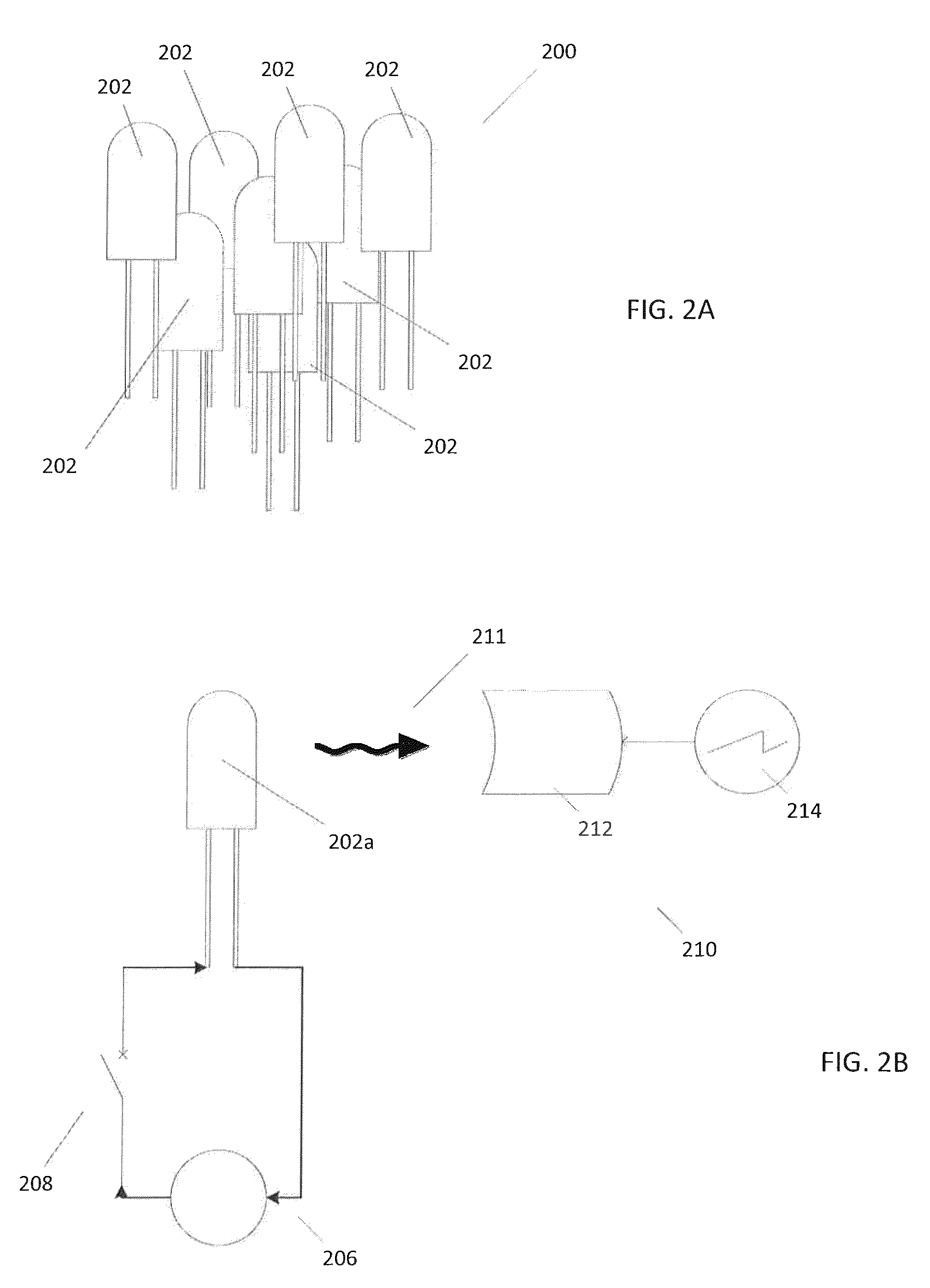
[0003]In one aspect, a method is disclosed that reduces the degree of variation in a group of light emitting diodes. In a typical implementation, the method includes providing a group of discrete light emitting diodes and testing each respective one of the light emitting diodes in the group to determine an optical power level produced by that light emitting diode when connected to an electrical power source. During testing, the electrical power source delivers a substantially identical amount of electrical current to each respective one of the light emitting diodes. The optical power level produced by the light emitting diodes during the test all fall within a first range of values. The method further includes connecting an electrical resistance in parallel with at least some of the light emitting diodes in the group to reduce an amount of optical power produced by those light emitting diodes. After the electrical resistances are connected, all of the optical power levels produced by the light emitting diodes fall within a second range that is narrower than the first range.
[0004]In some implementations, one or more of the following advantages are present.
[0005]For example, in some implementations, the techniques described herein reduce variations in optical power produced by different light emitting diodes in a group of similar or substantially similar light emitting diodes in a relatively simple and cost-efficient manner. This may help avoid the complexities, inefficiencies, time-consuming nature and tediousness of designing optical detectors and / or related circuitry to be able to accommodate wide variations in optical power levels, or binning light emitting diodes to categorize them according to the actual optical power each one produces. Moreover, implementing these techniques may help avoid the situation where it is not effective and / or possible to meet system design goals if the full distribution of light emitting diode output powers is used, thereby, resulting in the scrapping of some part of the distribution.

Problems solved by technology

Moreover, implementing these techniques may help avoid the situation where it is not effective and / or possible to meet system design goals if the full distribution of light emitting diode output powers is used, thereby, resulting in the scrapping of some part of the distribution.

Method used


Image

  • Light emitting diode output power control
  • Light emitting diode output power control
  • Light emitting diode output power control

Examples


Embodiment Construction

[0018]Commercially available light emitting diodes that are similar or substantially identical in design (e.g., those that are intended to be used in the same or substantially the same end applications) can sometimes produce widely varying optical power levels.

[0019]In some instances, the variation in optical power produced by different light emitting diodes having a particular type of design can be up to 300%. This relatively wide variation can lead to a variety of problems unless measures are taken to address the variation. Some of these measures may include, for example, designing optical detectors and / or related circuitry to be able to accommodate the wide variation in optical power levels, or binning light emitting diodes to categorize them according to the actual optical power each one produces. These approaches are less than ideal. For example, having to design optical detectors and / or related circuitry to accommodate wide variations in optical power from light emitting diode...


PUM


Abstract

A method of reducing variation in optical power levels across a group of light emitting diodes includes testing each respective one of the light emitting diodes to determine an optical power level produced by that light emitting diode when connected to an electrical power source. During testing, the electrical power source delivers a substantially identical amount of electrical current to each respective one of the light emitting diodes. The optical power levels from the test all fall within a first range of values. The method includes connecting an electrical resistance in parallel with at least some of the light emitting diodes to reduce an amount of optical power produced by those light emitting diodes. After the electrical resistances are connected, all of the optical power levels produced by the light emitting diodes fall within a second range that is narrower than the first range.

Description

FIELD OF THE INVENTION[0001]The present disclosure relates to light emitting diodes and, more particularly, relates to output power control of light emitting diodes.BACKGROUND[0002]Light emitting diodes having similar designs can sometimes produce very different optical power output levels. Typically, circuits that drive these light emitting diodes do so by providing constant or substantially constant electrical current (D.C. or pulsed) to the light emitting diodes.SUMMARY OF THE INVENTION[0003]In one aspect, a method is disclosed that reduces the degree of variation in a group of light emitting diodes. In a typical implementation, the method includes providing a group of discrete light emitting diodes and testing each respective one of the light emitting diodes in the group to determine an optical power level produced by that light emitting diode when connected to an electrical power source. During testing, the electrical power source delivers a substantially identical amount of el...

Claims


Application Information

Patent Timeline
Patent Type & Authority Patents(United States)
IPC IPC(8): H05B37/00G01J1/42H05B41/00H05B39/00H01L25/16
CPCG01J1/30G01J1/42H01L2224/48091H01L2924/00014G01J2001/4247H01L25/167H01L2224/48247H01L2933/0033H01L33/0095
Inventor GODFREY, LAWRENCEBARLOW, ARTHUR
Owner EXCELITAS TECH PHILIPPINES
Why Eureka
Try Eureka