Nanothermometer, methods and uses therefor

a technology of nanometers and other materials, applied in the field of nanometers, can solve the problems of increasing fluorescence, unquenching fluorescence of fluorophore, and sub-millimeter temperature measurement, and achieve the effect of increasing fluorescence and avoiding repetition

Inactive Publication Date: 2016-03-01
WASHINGTON UNIV IN SAINT LOUIS
View PDF4 Cites 4 Cited by
  • Summary
  • Abstract
  • Description
  • Claims
  • Application Information

AI Technical Summary

Benefits of technology

[0006]The present inventors have developed nanothermometers. A nanothermometer of the present teachings includes a non- or minimally-fluorescent nanoparticle which can exhibit an increase in fluorescence when the temperature of its environment reaches a critical temperature. In various configurations, the increase in fluorescence can be irreversible, i.e., following exposure to a critical (or greater) temperature which leads to an increase in fluorescence, a nanothermometer of these configurations does not decrease its fluorescence back to its original (i.e., pre-heated) level when temperature is reduced below the critical temperature. In various embodiments, irreversibility of fluorescence activation of a nanothermometer of the present teachings can be useful for highlighting treated regions and avoiding repetition of treatment over the same area.
[0011]In various embodiments, a nanothermometer of the present teachings can be used to measure temperature of a sample such as a biological sample, such as, without limitation, a tumor being subjected to therapeutic thermal ablation. In various configurations of these embodiments, a nanothermometer of the present teachings can be used to monitor tumor temperature in “real time,” such that, for example, a treatment provider (e.g., an oncologist) can more precisely determine the temperature of a tumor while performing a thermal ablation therapy procedure on a subject comprising a tumor.

Problems solved by technology

Temperature measurements on a sub-millimeter scale remain a significant challenge (Lee. J., et al.
The problem becomes especially apparent in thermal medical treatments such as tumor ablation when precise monitoring of temperature to minimize the damaging effects on healthy tissue is essential for the efficacy and safety of these procedures.
However, upon heating, the linker (with fluorophore attached) is released from the nanoparticle, thereby unquenching fluorescence of the fluorophore.
However, upon heating, fluorophore and / or quencher can be released from the particle surface, thereby leading to an increase in fluorescence.

Method used


Image

  • Nanothermometer, methods and uses therefor
  • Nanothermometer, methods and uses therefor
  • Nanothermometer, methods and uses therefor

Examples


example 1

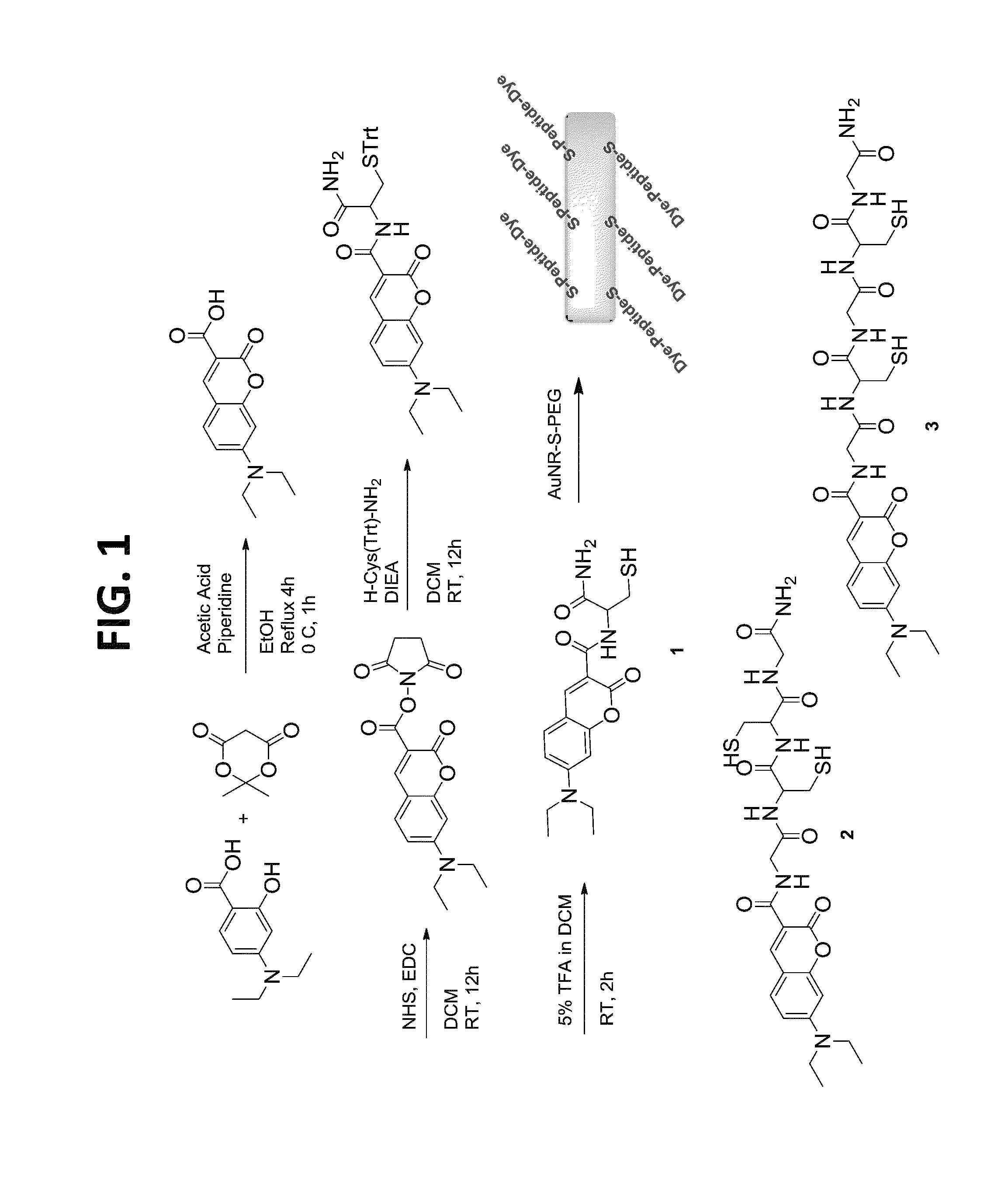
[0091]This example illustrates the synthesis of a dye-peptide conjugate of the present teachings.

[0092]The dye-peptide conjugates 1-3 were prepared using a standard solid state peptide synthesis protocol (FIG. 1). Briefly, Fmoc was removed from Rink amide resin with 20% piperidine in DMF with shaking and washed with DMF and DCM. After filtration DMF, Fmoc protected amino acid, DIEA, a solution of coupling reagents HOBT and HBTU in DMF were added. After the reaction was completed, the solvent was removed, and Fmoc was deprotected. The resin was washed, filtered and the next amino acid was added and the procedure repeated. After addition of the final amino acid, coumarin-NHS30 was added to the chain. The product was cleaved from the resin filtered and purified by reverse phase flash chromatography. A representative synthesis of compound 2: Fmoc was removed from 0.58 mmol Rink amide resin (0.10 g, 0.058 mmol loading) with 20% piperidine in DMF 3×10 minutes each with shaking. Deprotecte...

example 2

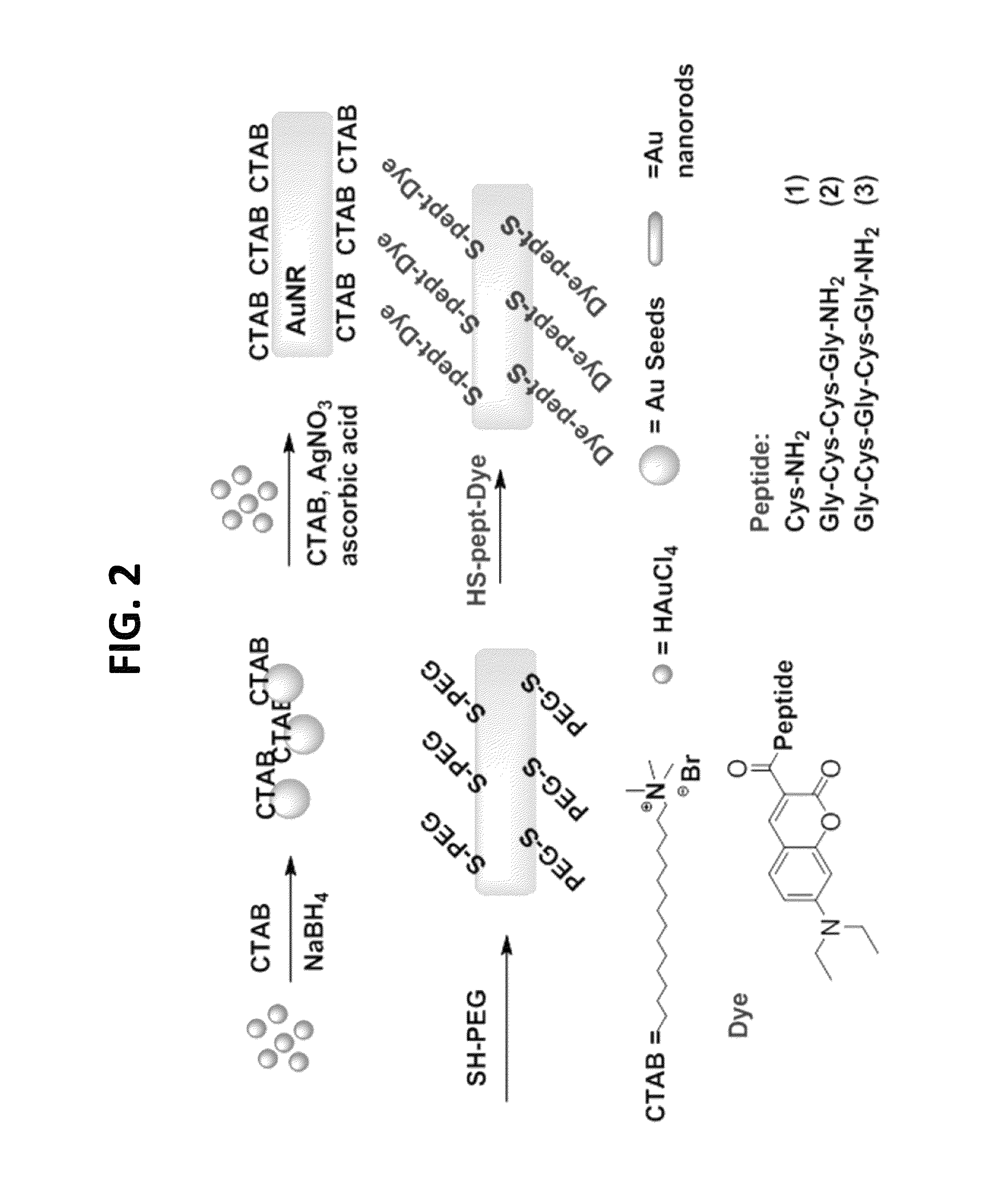
[0094]This example demonstrates the synthesis of a nanothermometer of the present teachings.

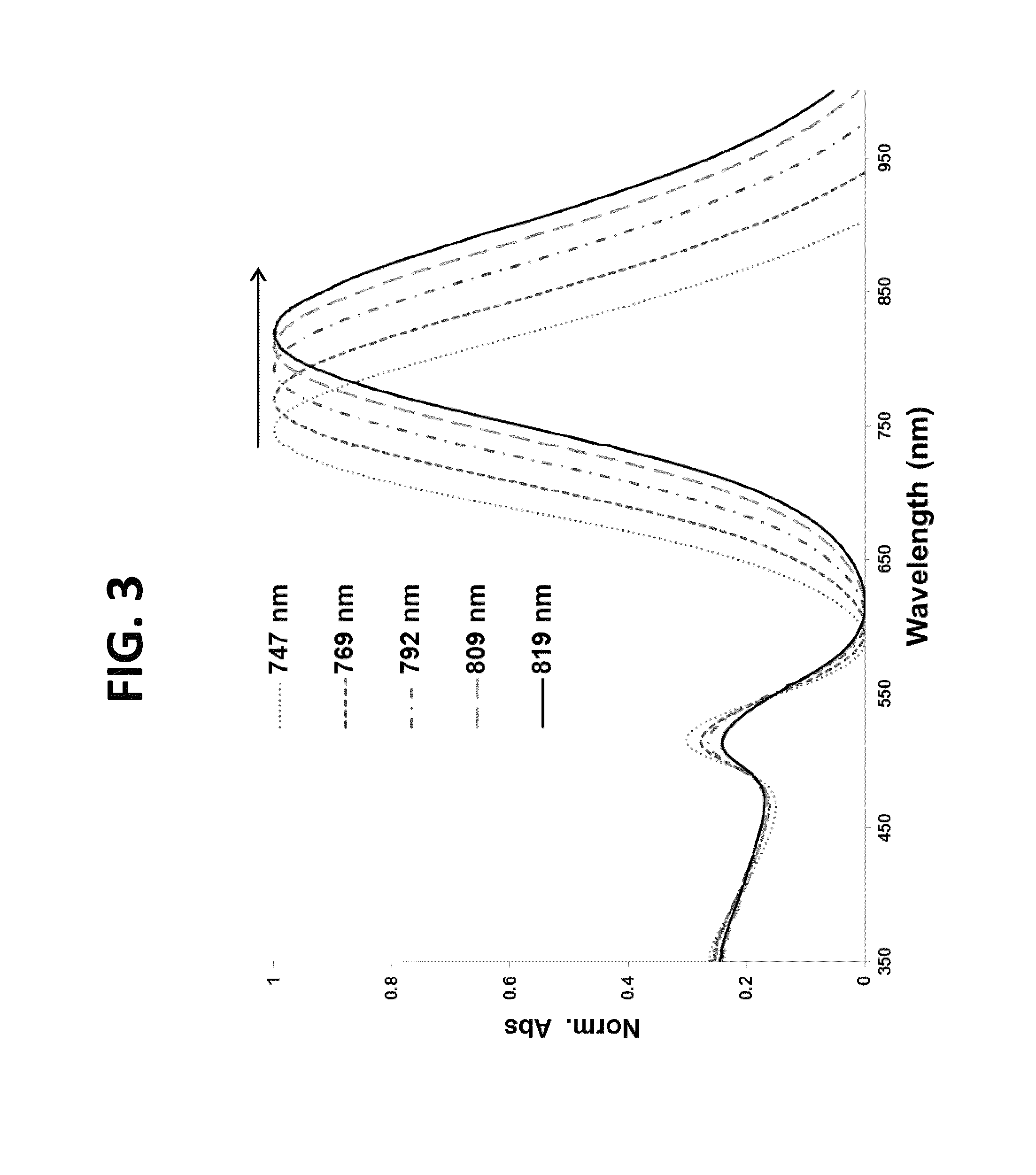
[0095]The overall design of the nanothermometers is shown in FIG. 7. The synthesis of the nanothermometers involved several convergent steps (FIG. 2). First, gold nanorods were prepared via an established procedure using a seed mediated synthesis in the presence of cetyl trimethyl ammonium bromide (CTAB) (See Chen, Y. S., et al., Nano Lett. 11: 348-54, 2011). Briefly, 5 mL of CTAB(aq) solution at 30-35° C. (0.2 M) was first mixed with 5 mL of HAuCl4(aq) solution (0.5 mM) with stirring. Then 0.60 mL of ice-cold NaBH4(aq) solution (0.01 M) was added to the mixture and vigorously stirred for 2 min at 30° C., which resulted in the formation of a brownish yellow seed solution. The growth solution was prepared by adding 0.15-0.2 mL AgNO3(aq) (4 mM) and then 5 mL of HAuCl4(aq) (1 mM) solutions to a 5 mL of CTAB(aq) at 30-35° C. (0.2 M) solution, under gentle mixing, followed by 70 μL of ascorbic aci...

example 3

[0100]This example illustrates evaluation of the synthesized nanothermometers.

[0101]In these experiments, following nanothermometer preparation, peptide-dye conjugates 1-3 were evaluated to determine the effect of i). the number of thiols and ii). the placement of thiols, relative to one another, within the linker. The temperature release profile was recorded for each sample in PBS buffer using two temperature ramps—slow, linear ramp 0.9° C. / min of heating, total 60 min. and fast, non-linear ramp from 20 to 85° C., total 8 min (FIG. 9, FIG. 10) While the first is better suited for kinetic measurements of peptide-dye conjugate release, the latter is more relevant for thermal ablations in clinics. Corresponding data were obtained using a standard fluorescence spectrophotometer with a temperature controlled cuvette holder and by using a thermal ablation imager.

[0102]In these experiments, nanothermometers were dispersed into PBS, pH 7.0 and subject to heating-cooling cycle. For slow tem...


PUM

PropertyMeasurementUnit
temperatureaaaaaaaaaa

Abstract

A nanothermometer is disclosed. In various embodiments, a nanothermometer comprises a nanoparticle such as a gold nanoparticle, a fluorophore, and a linker, such as a peptide linker, extending between the nanoparticle and the fluorophore, whereby the fluorophore is self-quenched. The linker can comprise one or more cysteines. An unheated thermometer shows little or no fluorescence. Upon heating, fluorophore-linker conjugates are released from the nanoparticle, thereby unquenching the fluorescence. An increase in fluorescence results. In some embodiments, the increase in fluorescence can be irreversible. Methods of measuring temperature of a sample such as a biological sample, and methods of synthesizing a nanothermometer, are also disclosed. A molecular thermometer is also disclosed.

Description

PRIORITY[0001]This application claims the benefit of priority to U.S. Provisional patent application 61 / 730,881 filed Nov. 28, 2012. This application is incorporated by reference in its entirety.GOVERNMENT SUPPORT[0002]This work received support from NIH / NCI grant R21CA149814. The government may have certain rights in the invention.INTRODUCTION[0003]Clinical thermometry of the human body is one of the most fundamental and successful techniques in healthcare. Temperature measurements on a sub-millimeter scale remain a significant challenge (Lee. J., et al. Angew. Chem. Int. Ed. Engl. 44: 7439-42, 2005; Lee, J. and Kotov, N. A., Nano Today 2: 48-51, 2007; Jaque, D. and Vetrone, F., Nanoscale. 4: 4301-26, 2012; Vetrone, F., et al., ACS Nano. 4: 3254-8, 2010; Hsia, C. H., et al., ACS Nano. 5: 9511-22, 2011). The problem becomes especially apparent in thermal medical treatments such as tumor ablation when precise monitoring of temperature to minimize the damaging effects on healthy tissu...

Claims


Application Information

Patent Timeline
Patent Type & Authority Patents(United States)
IPC IPC(8): G01N21/76G01K11/20
CPCG01K11/20G01K2211/00
Inventor BEREZIN, MIKHAIL, YGUSTAFSON, TIFFANY, P
Owner WASHINGTON UNIV IN SAINT LOUIS
Why Eureka
Try Eureka