Fly eye lens and proximity exposure machine optical system

a technology of proximity exposure machine and optical system, which is applied in the field of optics, can solve the problems of poor uniformity of critical dimensions of patterns exposed by the above-mentioned optical system, further and affecting the quality of color filters

Active Publication Date: 2016-03-01
BOE TECH GRP CO LTD +1
View PDF9 Cites 0 Cited by
  • Summary
  • Abstract
  • Description
  • Claims
  • Application Information

AI Technical Summary

Benefits of technology

[0010]By providing a fly eye lens including a first lens assembly and a second lens assembly, wherein, the first lens assembly includes a plurality of lenses forming the first lens face, the second lens assembly includes a plurality of lenses forming the second lens face, among the plurality of lenses in the second lens assembly, a lens closer to the center of the second lens face has a higher transmittivity; and a lens farther from the center of the second lens face has a lower transmittivity, the embodiment of the present invention has the following advantageous effects. When the proximity exposure machine performs the exposure, the critical dimension of the exposed pattern is generally increased as the illuminance (exposure amount) is increased and is reduced as the exposure distance is reduced, but since the lenses in the second lens assembly have different transmittivities, the illuminances at different positions, to which the second lens face radiates light beams, on the mask plate are different so that the change in critical dimensions of the patterns due to different exposure distances at respective positions on the mask plate can be relatively compensated. The fly eye lens of the present invention and the proximity exposure machine optical system including the fly eye lens can be used to improve the uniformity of the critical dimensions of the exposed patterns to a certain extent.
. When the proximity exposure machine performs the exposure, the critical dimension of the exposed pattern is generally increased as the illuminance (exposure amount) is increased and is reduced as the exposure distance is reduced, but since the lenses in the second lens assembly have different transmittivities, the illuminances at different positions, to which the second lens face radiates light beams, on the mask plate are different so that the change in critical dimensions of the patterns due to different exposure distances at respective positions on the mask plate can be relatively compensated. The fly eye lens of the present invention and the proximity exposure machine optical system including the fly eye lens can be used to improve the uniformity of the critical dimensions of the exposed patterns to a certain extent.

Problems solved by technology

In other words, the critical dimensions of the patterns exposed by the above-mentioned optical system have a poor uniformity.
It can be seen from the above fabricating manner that when the proximity exposure machine optical system performs the exposure, the bending of the mask plate causes exposure distances in respective regions to vary so that the critical dimensions of the patterns exposed on the substrate have a poor uniformity and the quality of the color filter is further affected.

Method used


Image

  • Fly eye lens and proximity exposure machine optical system
  • Fly eye lens and proximity exposure machine optical system
  • Fly eye lens and proximity exposure machine optical system

Examples


Embodiment Construction

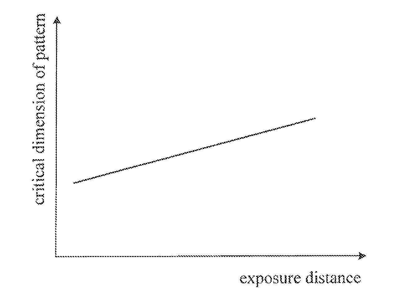
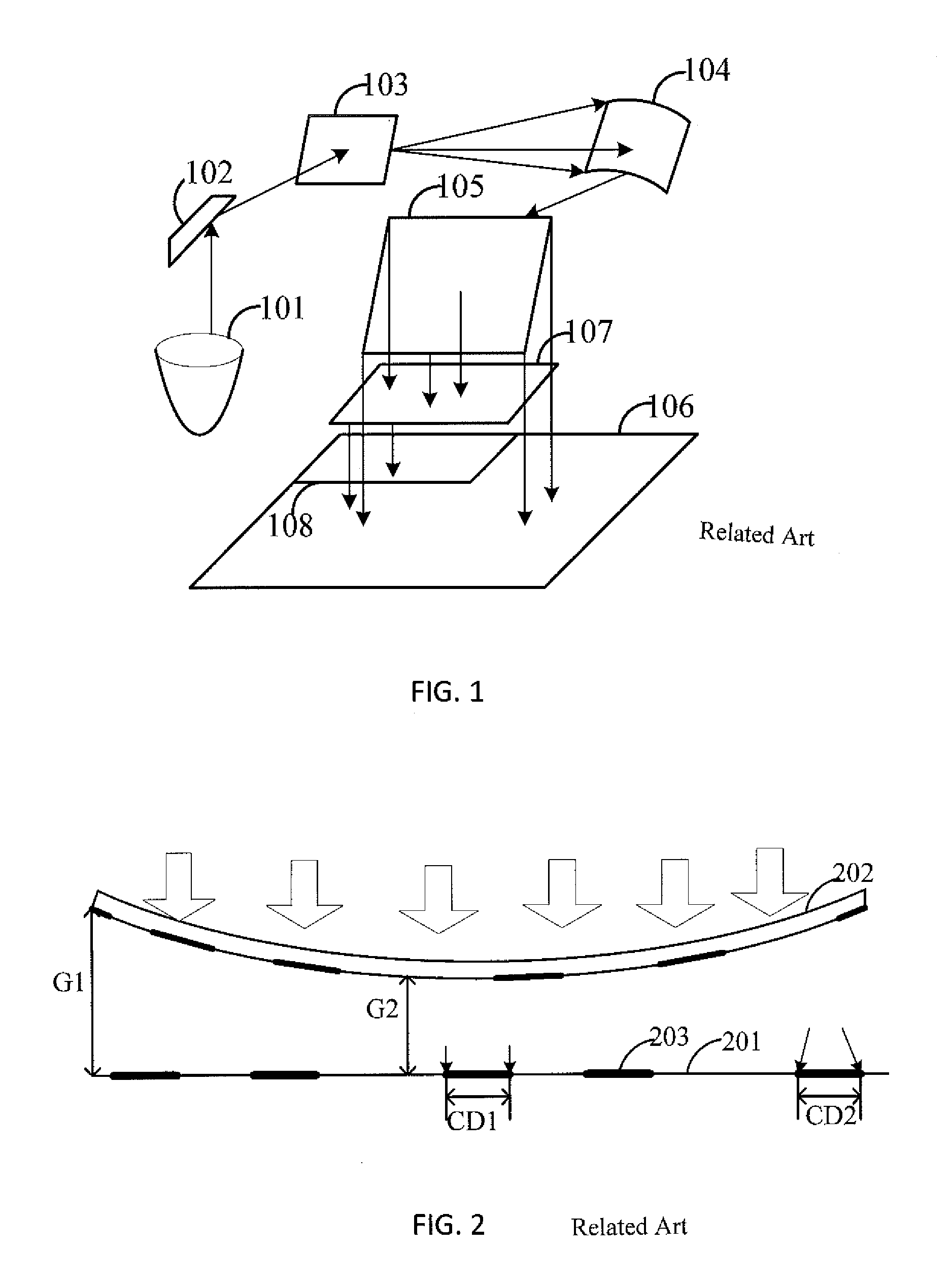
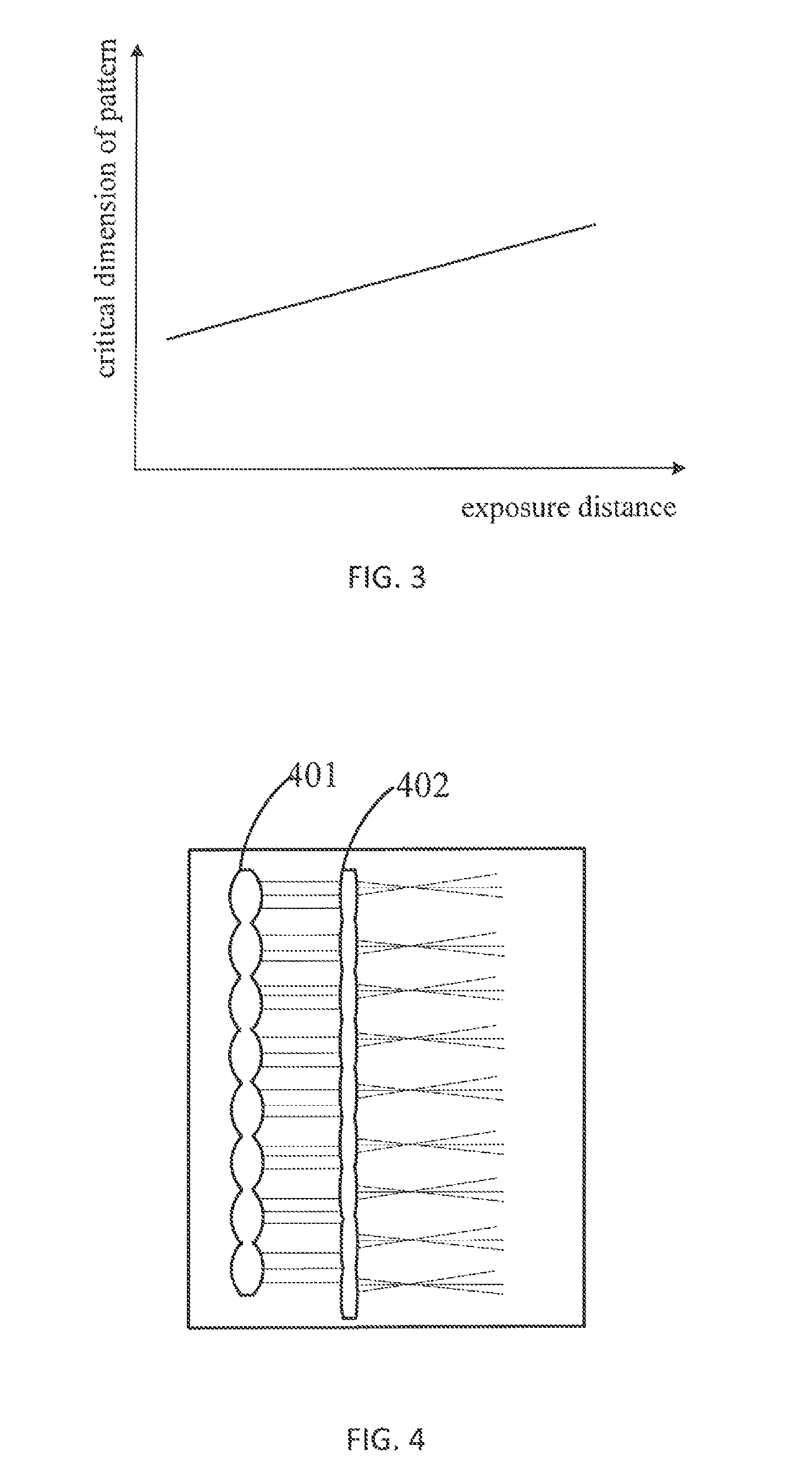
[0019]An existing mask plate is bent when a proximity exposure machine optical system performs exposure, and as a result, the exposure distance in a central region of the mask plate (i.e., a distance in a vertical direction between the central region and a substrate of the proximity exposure machine) is shorter than that in an edge region of the mask plate. Thus, in a case where other conditions, such as exposure amount, are fixed, the critical dimension of a pattern exposed on a central region of the substrate is smaller than that of a pattern exposed on an edge region of the substrate so that the critical dimensions of the exposed patterns have a poor uniformity. In view of the above problem, the present invention provides a fly eye lens which can be used to improve the uniformity of the critical dimensions of the exposed patterns to a certain extent.

[0020]The specific implementing manner of the fly eye lens according to an embodiment of the present invention will be described in ...


PUM

PropertyMeasurementUnit
transmittivitiesaaaaaaaaaa
distanceaaaaaaaaaa

Abstract

An embodiment of the present invention provides a fly eye lens which is applied to a proximity exposure machine optical system. The fly lens includes a first lens assembly and a second lens assembly, wherein the first lens assembly includes a plurality of lenses which form a first lens face, and the second lens assembly includes a plurality of lenses which form a second lens face. The first lens face is used to split an incident broad light beam into narrow light beams and then refract the narrow light beams onto the second lens face, and the second lens face is used to dispersively refract the received narrow light beams onto a concave mirror in the optical system. A lens closer to a center of the second lens face has a higher transmittivity, and a lens farther from the center of the second lens face has a lower transmittivity. According to the embodiment of the present invention, since different lenses on the second lens face have different transmittivities, the illuminances of light radiated to different regions of a mask plate through the fly eye lens are different, and thus the uniformity of the critical dimensions of the exposed patterns can be improved to a certain extent.

Description

FIELD OF THE INVENTION[0001]The present invention relates to the field of optics, and more particularly, to a fly eye lens and a proximity exposure machine optical system.BACKGROUND OF THE INVENTION[0002]With development of display technology, a display device with large size, high quality and low cost is the trend. Quality of a color filter which is a major component of a display device (for example, a TFT-LCD display device) determines the display effect of the display device.[0003]At present, a proximity exposure machine optical system is mostly used to perform exposure when fabricating a color filter. Specifically, as shown in FIG. 1, the above mentioned optical system includes an exposure lamp 101, a first planar mirror 102, a fly eye lens 103, a concave mirror 104 and a second planar mirror 105, and further includes a mask plate 106, a substrate 107, an exposure region 108 and a photoresist (not shown in FIG. 1). In this optical system, the exposure lamp 101 is mainly used to ...

Claims


Application Information

Patent Timeline
Patent Type & Authority Patents(United States)
IPC IPC(8): G03F7/20
CPCG03F7/70083G03F7/7035G03F7/70058G03F7/70066G03F7/70075
Inventor LI, MINWU, HONGJIANGLEE, GYUHYUNZHANG, JIKAIYANG, TONGHUA
Owner BOE TECH GRP CO LTD
Why Eureka
Try Eureka