Relay having two switches that can be actuated in opposite directions

a technology of relays and switches, applied in the field of electromagnetical relays, can solve the problems of inability to use separate diagnostic switches on one side of relays and load switches on the other side of relays, and achieve the effect of avoiding damage to the coil assembly in the magnetization process and simplifying the manufacturing of relays

Active Publication Date: 2016-03-01
PHOENIX CONTACT GMBH & CO KG
View PDF20 Cites 33 Cited by
  • Summary
  • Abstract
  • Description
  • Claims
  • Application Information

AI Technical Summary

Benefits of technology

[0012]With respect to the configuration of the relay, a rocking armature system is preferred. The contacts of the two switches are disposed on opposite ends of the coil with respect to the longitudinal extension thereof and move transversely to the longitudinal extension when the relay is switched. The first leg of the rocking armature is coordinated with the first switch, and the second leg of the rocking armature with the second switch, and this in such a manner that when the respective switch is moved downwards the switch is closed, and when moved upwards the switch is opened. Therefore, the contact sets of the switches take antivalent switching states. The first switch near the armature is operated as a break contact switch, and the second switch used as a load switch is operated as a make contact switch. Further, the load switch which is driven through the coupling member is actuated by a spring attached to the armature and driving the coupling element. In this manner, the break contact function and make contact function of the load switch is improved.
[0014]The relay according to the invention may comprise a pole assembly and a coil assembly, which greatly simplifies the manufacturing of the relay. Specifically, the pole assembly may be produced with a magnetized permanent magnet before being combined with the coil assembly, thereby avoiding to damage the coil assembly in the magnetization process.
[0015]In a favorable design of the relay, the pole assembly and the fixed contacts of the switches are mounted in a support component. Preferably, the individual components of the pole assembly and the fixed contacts are embedded in plastic material within the support component.

Problems solved by technology

Power supply to the movable contacts is accomplished via each of the torsion springs and the leaf springs, so that a separate use as a diagnostic switch on one side of the relay and as a load switch on the other side of the relay is not possible.

Method used


Image

  • Relay having two switches that can be actuated in opposite directions
  • Relay having two switches that can be actuated in opposite directions
  • Relay having two switches that can be actuated in opposite directions

Examples


first embodiment

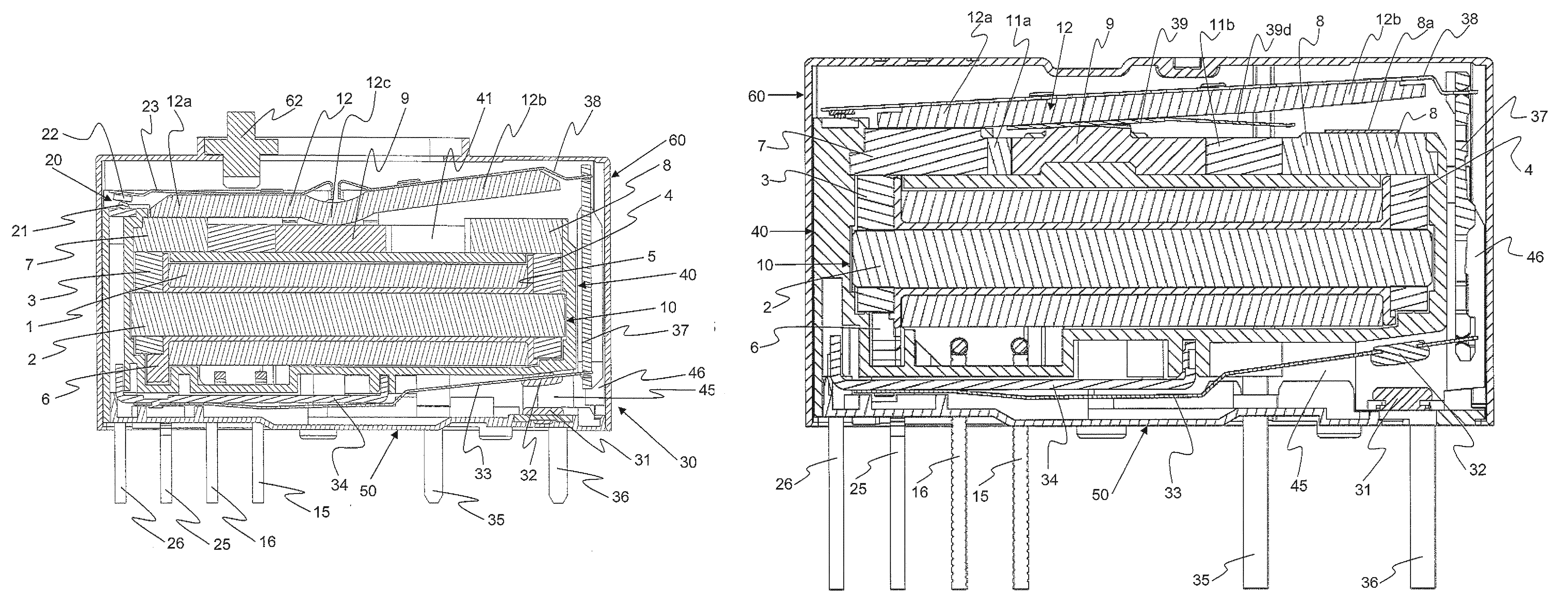
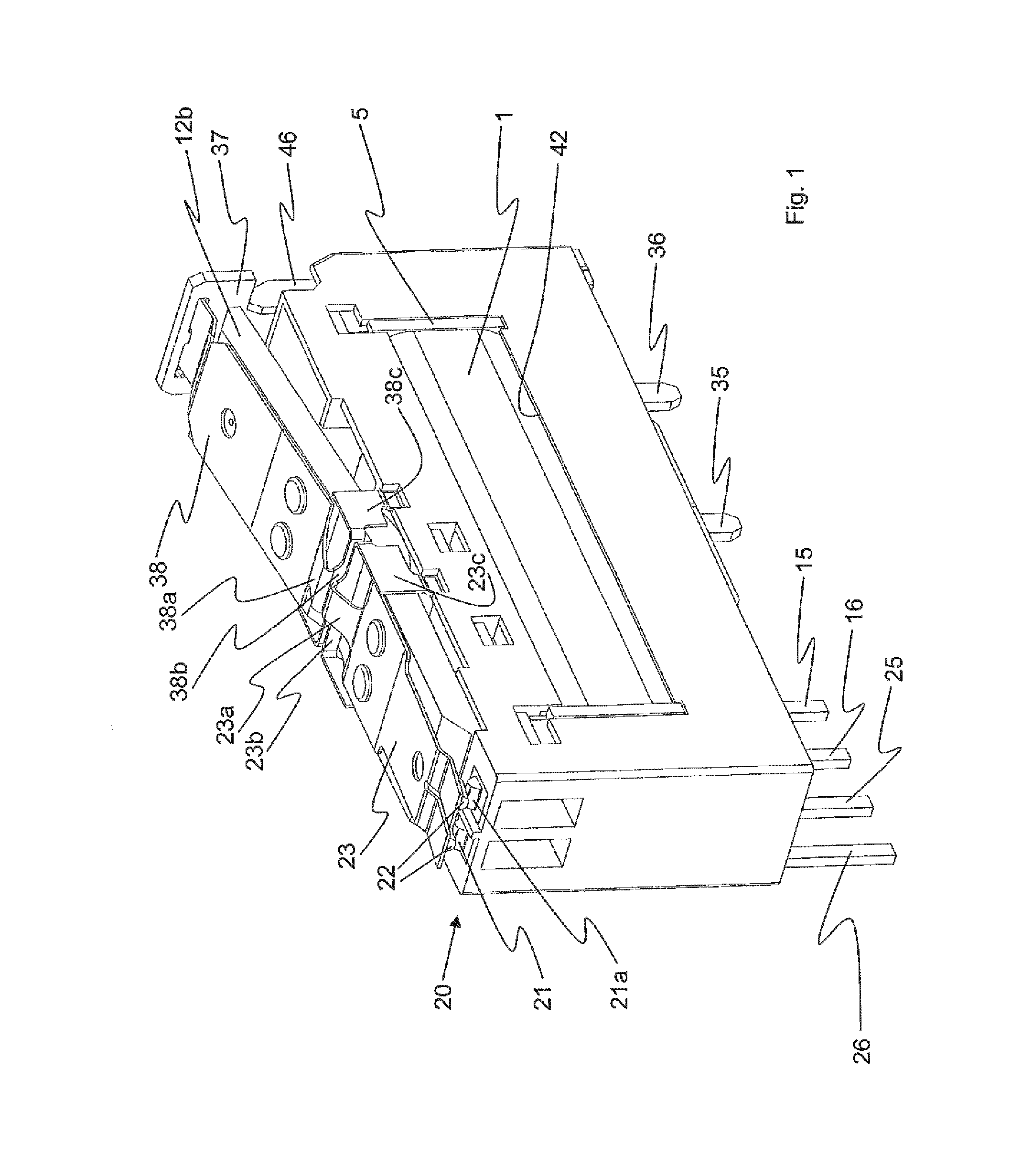
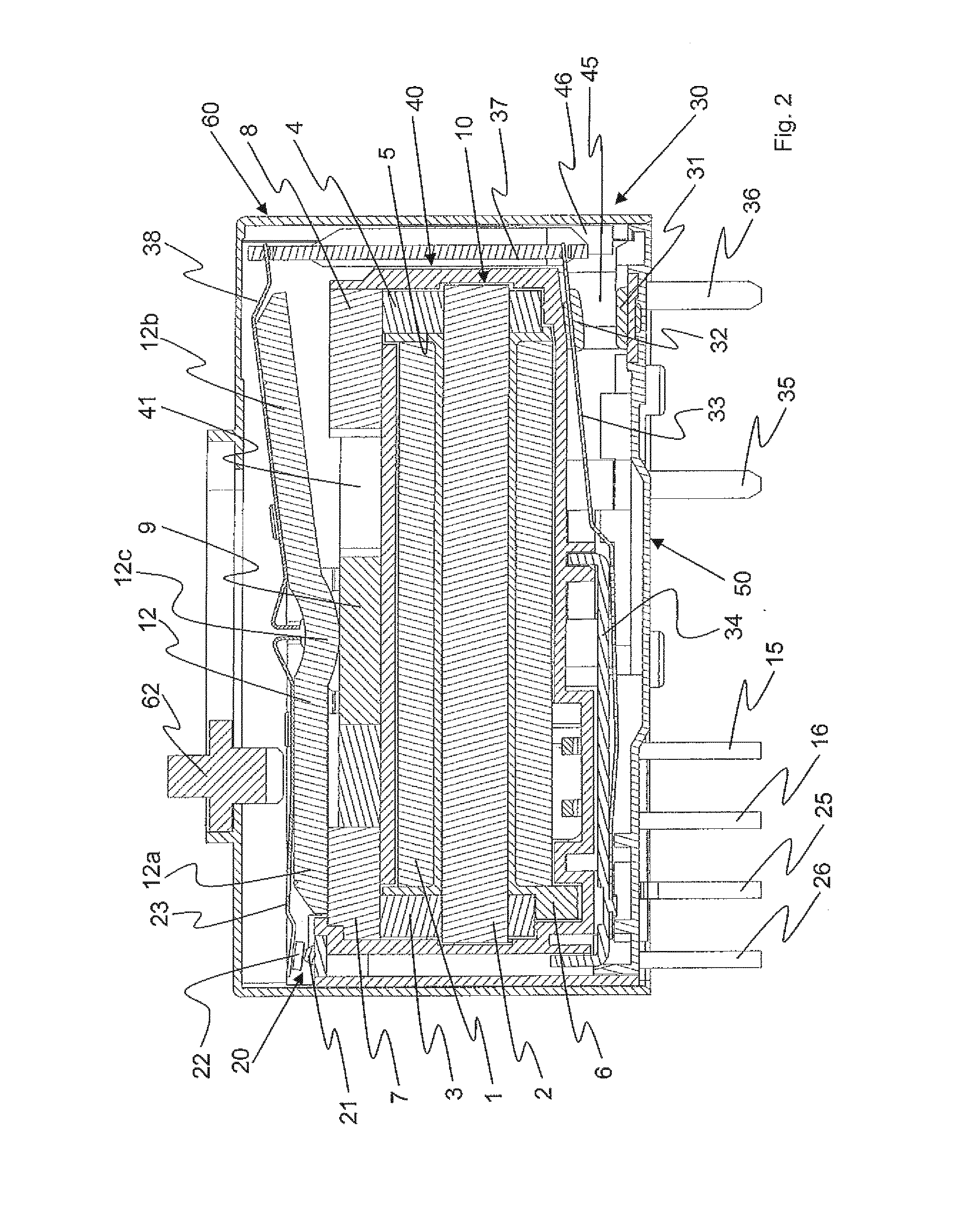
[0028]The electromagnetic relay comprises a magnetic system and a switch system (including a diagnostic switch 20 and a load switch 30), which are held together and protected by housing parts. The magnetic system comprises an electromagnet which is connected to a permanent magnet 11 and an armature 12 through magnetic flux pieces 7, 8, 9. The main part of the electromagnet is a coil assembly 10 consisting of a coil 1 wound around a support body 5, a ferromagnetic core 2, and ferromagnetic pole pieces 3 and 4 as a structural unit. The core 2 may be formed integrally with one of the pole pieces, or even integrally with both of the pole pieces. Magnetic flux pieces 7 and 8 define the poles of the electromagnet. Magnetic flux piece 9 forms a support piece for the armature 12 which is configured as a rocking armature here. In the relay, permanent magnet 11 is configured with two poles and may be arranged at the end of the switch 20 as illustrated, or at the opposite end.

[0029]In the exem...

second embodiment

[0044]In the relay, permanent magnet 11 comprises two portions 11a and 11b, and interposed therebetween a magnetic flux piece 9 of soft iron so as to form a three-pole permanent magnet. Portion 11a has a higher coercive force when compared to portion 11b. The two portions 11a and 11b have the same polarity towards magnetic flux piece 9, that means either both are aligned with the south pole facing magnetic flux piece 9, or both with the north pole, while towards the outer ends of the relay, the permanent magnet 11 with a total of three poles presents only north poles, or only south poles, as the case may be. Magnetic flux piece 9 presents the adjacent polarity, i.e. south pole if the north pole of the permanent magnet faces outwards, and north pole if the south pole of the permanent magnet faces outwards.

[0045]In the second embodiment, the mounting of armature 12 is different from the first embodiment in that a cross-shaped spring 39 provides for the support of armature 12 on magnet...


PUM


Abstract

An electromechanical relay is provided, comprising a magnetic system and a pivotable armature. A diagnostic switch is arranged on one side of the relay, and the set of contacts of the diagnostic switch is driven by the adjacent leg of the armature. A load switch is arranged on the bottom side of the relay and is driven by the second leg of the armature via an insulating coupling member.

Description

FIELD OF THE INVENTION[0001]The invention relates to an electromagnetic relay comprising an electromagnetic system, an armature, a first switch, and a second switch.BACKGROUND OF THE INVENTION[0002]Prior art relays of this type (EP 0 197 391 A2; U.S. Pat. No. 4,703,293 A; U.S. Pat. No. 6,107,903 A) include an electromagnetic system having at least a coil, a coil core, and two pole pieces defining two opposing ends of the relay. The relay housing has fixed contacts of the switches at the opposing ends of the relay. The movable contacts of the switches are located at the end of contact springs which are connected via conductive spring elements in the central region of the relay to a respective active current connection. Two parallel contact springs are provided, with a total of four contacts for actuating four switches which are located on the upper side of the relay in corner positions.[0003]From U.S. Pat. No. 6,670,871 B1 a polarized relay is known, which comprises a main body inclu...

Claims


Application Information

Patent Timeline
Patent Type & Authority Patents(United States)
IPC IPC(8): H01H50/54H01H50/18H01H50/02H01H50/14H01H51/22H01H50/64
CPCH01H50/54H01H50/02H01H50/14H01H50/18H01H50/541H01H51/2236H01H50/642H01H51/229H01H51/2272H01H51/2281
Inventor HOFFMANN, RALFHEINRICH, JENSMUELLER, CHRISTIANABEL, OLAFKUEHNE, THOMAS
Owner PHOENIX CONTACT GMBH & CO KG
Why Eureka
Try Eureka