Exhaust device of fuel cell vehicle

a fuel cell and exhaust pipe technology, applied in the direction of battery/cell propulsion, electrochemical generator, electric propulsion mounting, etc., can solve the problem of water likely to enter the exhaust port, and achieve the effect of reducing the length of the exhaust passage including the exhaust duct, reducing the air-flow resistance of the exhaust passage, and facilitating the discharge of excess air

Active Publication Date: 2016-03-08
SUZUKI MOTOR CORP
View PDF7 Cites 13 Cited by
  • Summary
  • Abstract
  • Description
  • Claims
  • Application Information

AI Technical Summary

Benefits of technology

[0013]Regarding the exhaust device of a fuel cell vehicle of the present invention, a downstream end portion of the exhaust passage opens above the front hood. As a result, the length of the exhaust passage including the exhaust duct can be reduced. Therefore, the air-flow resistance of the exhaust passage can be reduced. Accordingly, it is possible to smoothly discharge the excess air and the excess hydrogen from the fuel cell to the exterior of the vehicle, and it is possible to smoothly draw air into the intake duct.
[0014]Regarding the exhaust device of a fuel cell vehicle of the present invention, a portion of the exhaust passage which extends from the exhaust port of the exhaust duct to the opening portion of the cover, is curved, and the opening portion is positioned above the upper surface of the front hood so as to be away from the upper surface thereof. Accordingly, intrusion of water into the exhaust duct from the outside can be prevented.

Problems solved by technology

However, when the exhaust port opens upward, water is likely to intrude into the exhaust port.

Method used


Image

  • Exhaust device of fuel cell vehicle
  • Exhaust device of fuel cell vehicle
  • Exhaust device of fuel cell vehicle

Examples


embodiment

[0021

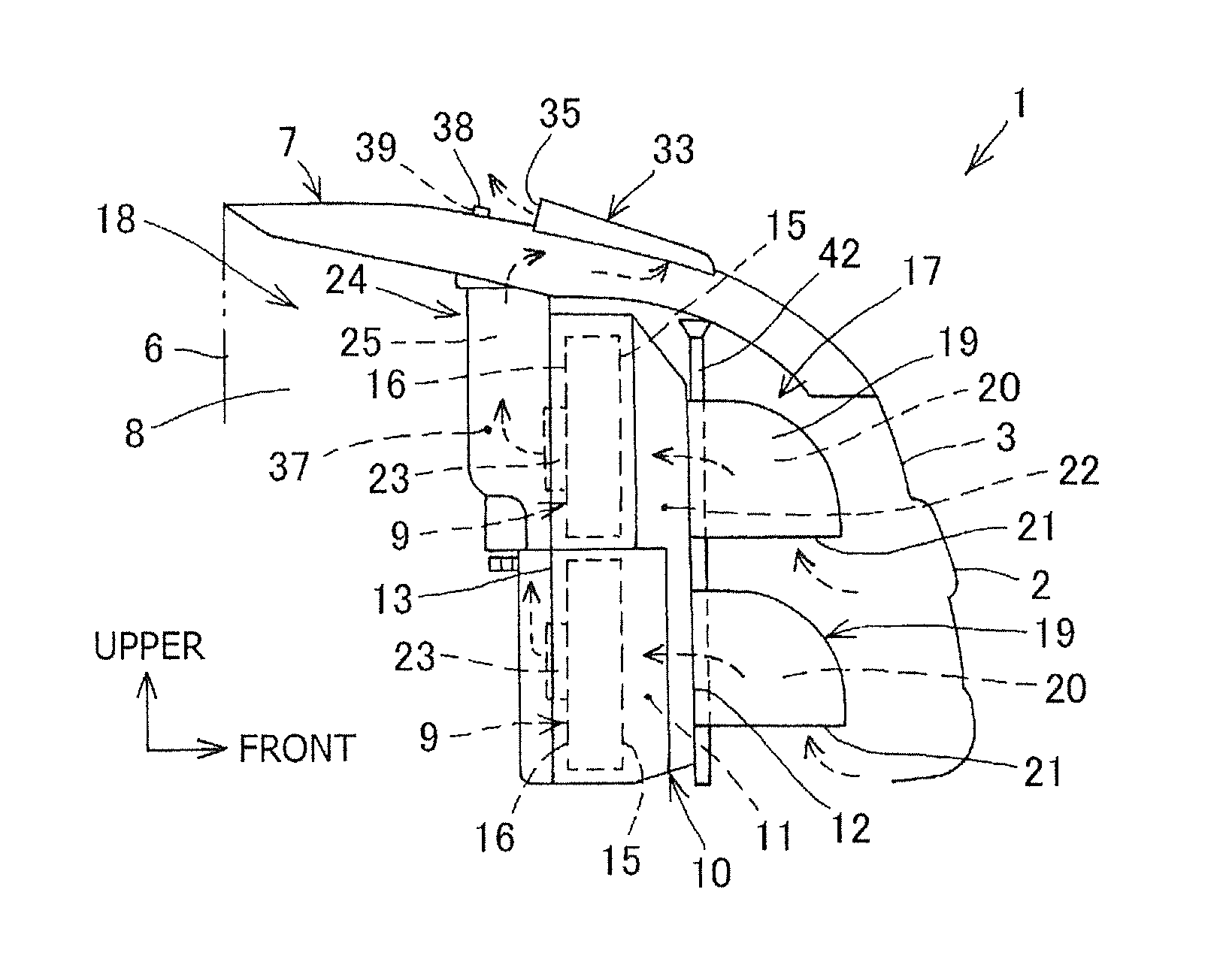
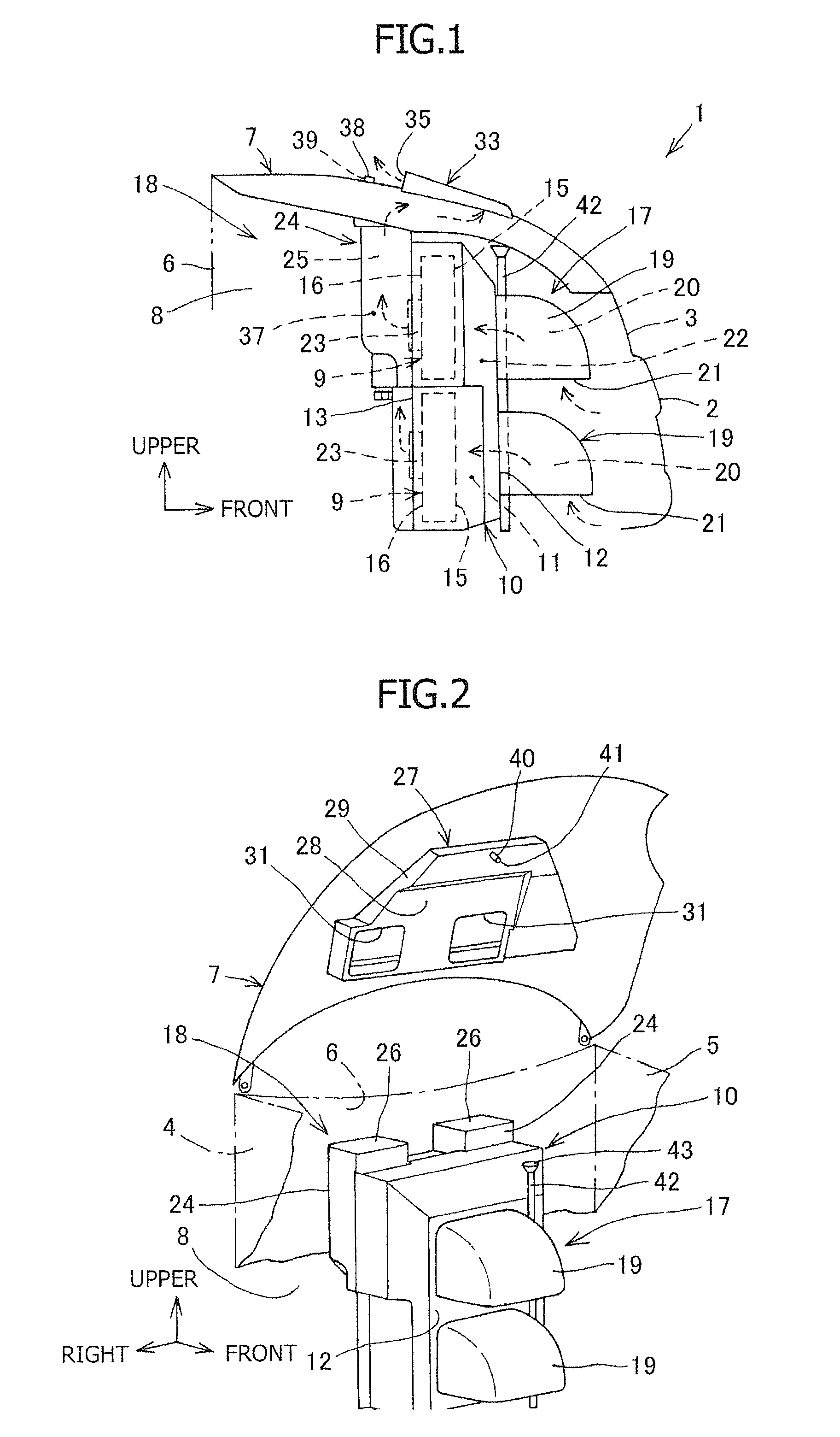
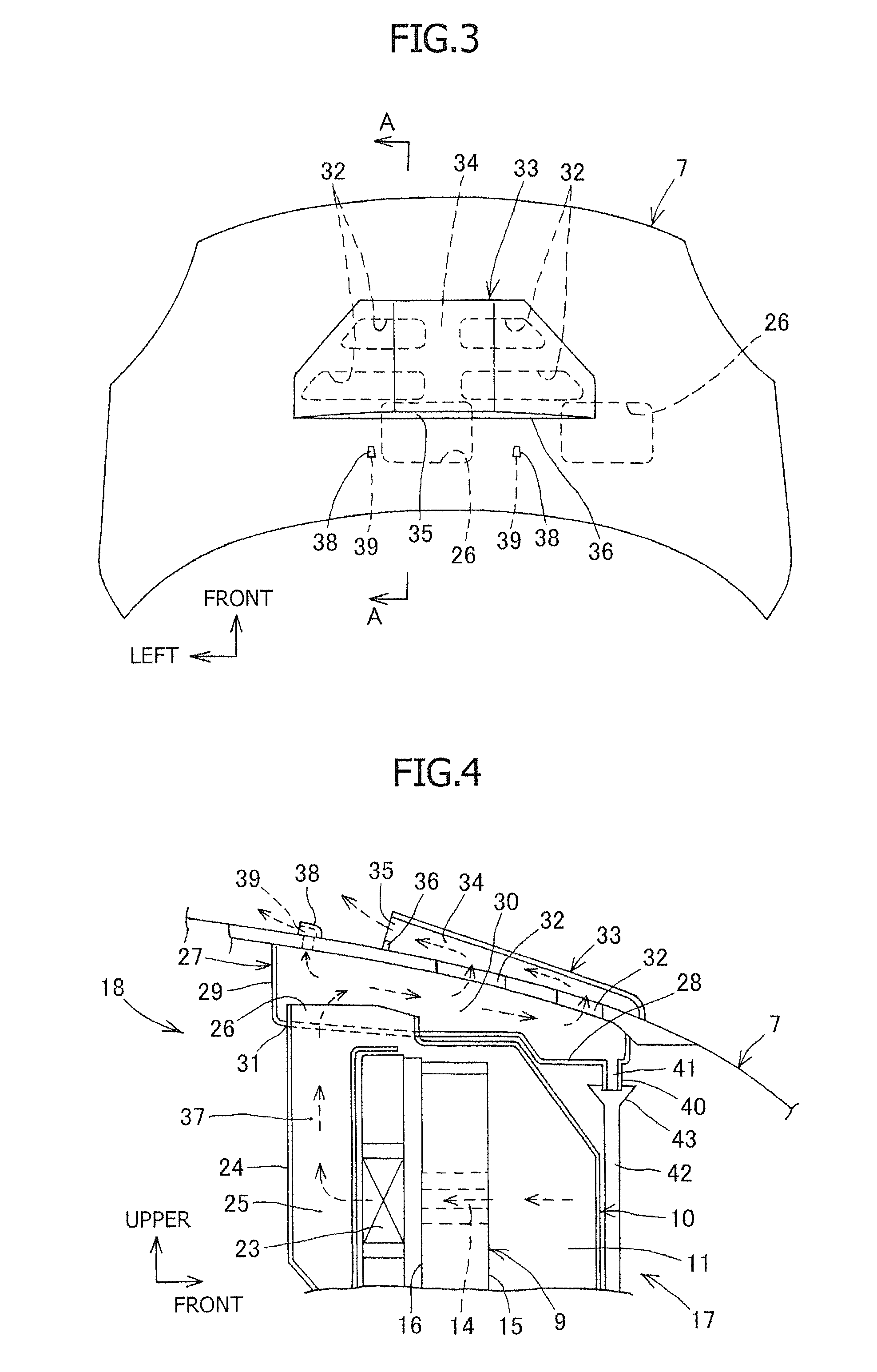
[0022]FIGS. 1 to 5 illustrate the Embodiment of the present invention. In FIGS. 1 and 2, reference numeral “1” denotes a fuel cell vehicle, reference numeral “2” denotes a front bumper, reference numeral “3” denotes a front grille, reference numeral “4” denotes a right side panel, reference numeral “5” denotes a left side panel, reference numeral “6” denotes a dash panel, reference numeral “7” denotes a front hood, and reference numeral “8” denotes a front compartment. The fuel cell vehicle 1 is a four-wheel vehicle. The fuel cell vehicle 1 is provided with the front compartment 8 in a space which is formed on a front portion of the vehicle, this front portion is surrounded by the front bumper 2, the front grille 3, the right side panel 4, the left side panel 5, and the dash panel 6, and furthermore, the front portion is covered with the front hood 7 from above. A fuel cell case 10 housing fuel cells 9 is arranged in the front compartment 8.

[0023]The fuel cell case 10 is formed...


PUM

PropertyMeasurementUnit
heightaaaaaaaaaa
widthaaaaaaaaaa
temperatureaaaaaaaaaa

Abstract

To achieve smooth drawing of air into a fuel cell, the air-flow resistance of an exhaust passage is reduced and intrusion of water into an exhaust duct is prevented. In the present invention, in an exhaust device of a fuel cell vehicle, an exhaust chamber is attached to a lower surface of the front hood, the exhaust duct extends upward in a vertical direction from a rear portion of a fuel cell case, an exhaust port at an upper end of the exhaust duct opens to an interior of the exhaust chamber, a penetrating hole through which the inside of the exhaust chamber communicates with the outside space, is formed in the front hood in a portion in front of the exhaust port in a vehicle front and rear direction, the penetrating hole is covered with a cover, and an opening portion opening toward a rear side of the vehicle and being positioned above and away from an upper surface of the front hood, is formed in the cover.

Description

CROSS-REFERENCE TO RELATED APPLICATIONS[0001]This application is a national stage application filed under 35 U.S.C. 371 of International Application No. PCT / JP2012 / 055045, filed Feb. 29, 2012, which claims priority from Japanese Patent Application No. 2011-084160, filed Apr. 6, 2011, each of which is incorporated by reference herein in its entirety.TECHNICAL FIELD[0002]The present invention relates to an exhaust device of a fuel cell vehicle. In particular, the present invention relates to an exhaust device of a fuel cell vehicle which can achieve smooth intake and exhaust of a fuel cell and can prevent intrusion of water.BACKGROUND ART[0003]In a kind of fuel cell vehicle, a fuel cell including a fuel cell stack, which is formed by stacking a plurality of fuel-cell cells, is used as a drive energy source. In this fuel cell vehicle, air used as a reaction gas is supplied to the fuel cell which is housed in a fuel cell case, by use of an intake duct. After that, the air is made to rea...

Claims


Application Information

Patent Timeline
Patent Type & Authority Patents(United States)
IPC IPC(8): H01M8/04B60K1/04B60K11/08B60K13/02H01M8/24B60K13/04
CPCH01M8/04761B60K1/04B60K11/08B60K13/02H01M8/04089H01M8/2485B60K13/04B60K2001/0411H01M2250/20Y02E60/50Y02T90/32H01M8/2484Y02T10/70Y02T90/40B60K8/00B60L50/50H01M8/00H01M8/04
Inventor OZAWA, NAOKIMATSUMOTO, SHIROIKEYA, KENGO
Owner SUZUKI MOTOR CORP
Why Eureka
Try Eureka