
Therapeutic ultrasound system

a technology of ultrasound system and therapeutic device, which is applied in the field of medical equipment, can solve the problems of transmission wire breaking, heat buildup, and increased fatigue experienced by transmission wire at certain critical locations

Active Publication Date: 2016-03-15
FLOWCARDIA
View PDF323 Cites 36 Cited by
  • Summary
  • Abstract
  • Description
  • Claims
  • Application Information

AI Technical Summary

Benefits of technology

The present invention is about improving a way to cool the transmission wire of an ultrasound device during a medical procedure. The technical effect is to prevent overheating and ensure better performance of the ultrasound device during the procedure.

Problems solved by technology

However, all of these systems and devices generally encounter three types of problems which are not always adequately addressed by these systems and devices.
One type of problem relates generally to the effective transmission of ultrasound energy from an ultrasound source to the distal tip of the device where the ultrasound energy is applied to ablate or remove obstructive material.
This transmission of increased energy along the transmission wire may increase the fatigue experienced by the transmission wire at certain critical locations, such as at the connection between the transducer and the transmission wire.
This fatigue and any associated stress may cause the transmission wire to break.
Another type of problem relates to the heat that is built up from the transmission of ultrasound energy along the transmission wire.
However, during the delivery of ultrasound energy, the temperature of the transmission wire may reach 100 to 200 degrees Celsius, at which the transmission wire may lose its superelasticity and may experience mechanical deformations at portions that are bent when exposed to the high temperatures.
The high temperatures may also cause the propagated energy to be lost more rapidly and transferred to heat, thereby reducing the efficacy of the ultrasound transmission wire.
However, there are two limitations to this approach.
In addition to these two limitations, increased irrigation fluid pressure may cause local tissue damage.

Method used


Image

  • Therapeutic ultrasound system
  • Therapeutic ultrasound system
  • Therapeutic ultrasound system

Examples


Embodiment Construction

[0021]The following detailed description is of the best presently contemplated modes of carrying out the invention. This description is not to be taken in a limiting sense, but is made merely for the purpose of illustrating general principles of embodiments of the invention. The scope of the invention is best defined by the appended claims.

[0022]In certain instances, detailed descriptions of well-known devices, compositions, components, mechanisms and methods are omitted so as to not obscure the description of the present invention with unnecessary detail.

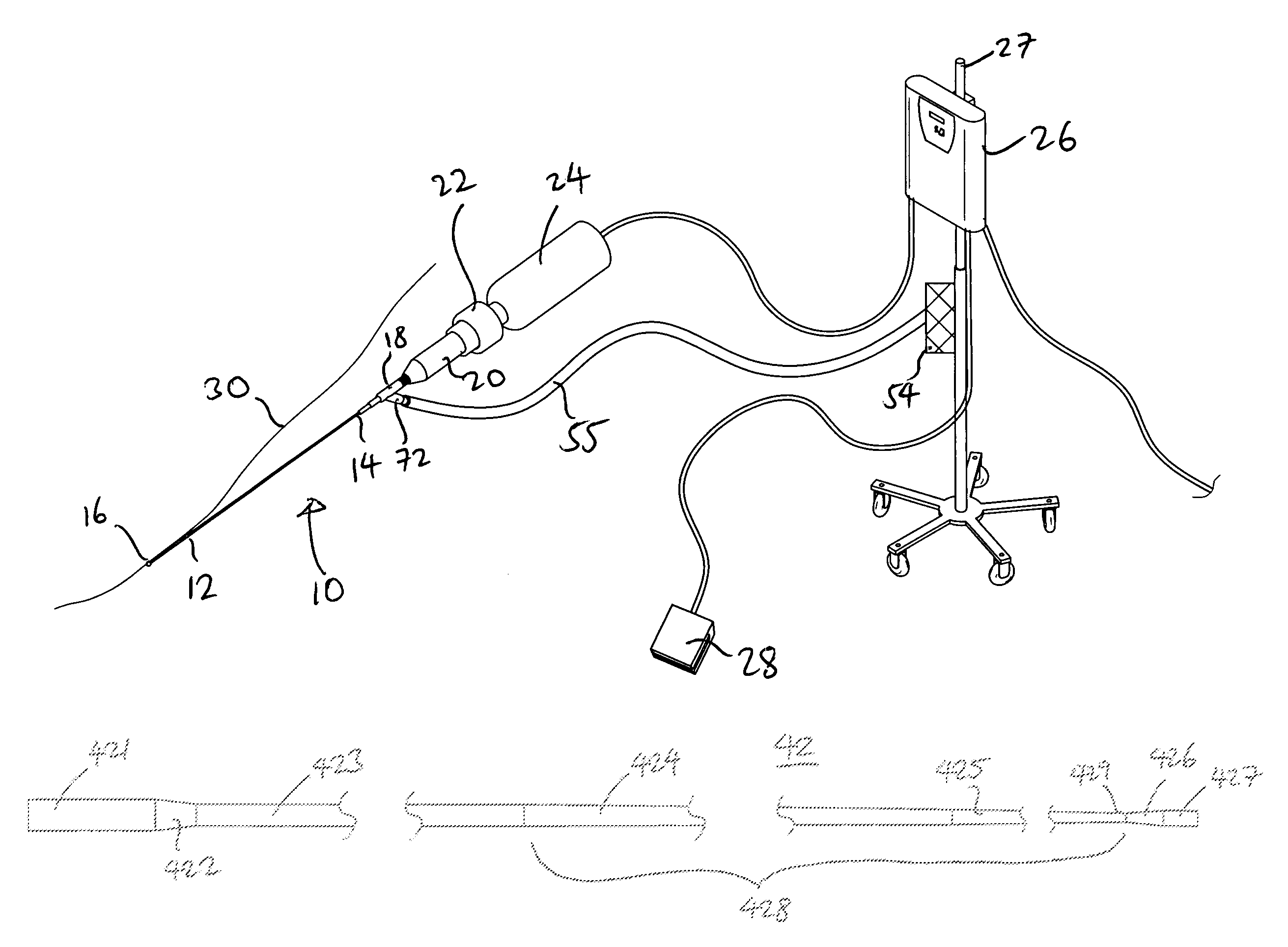
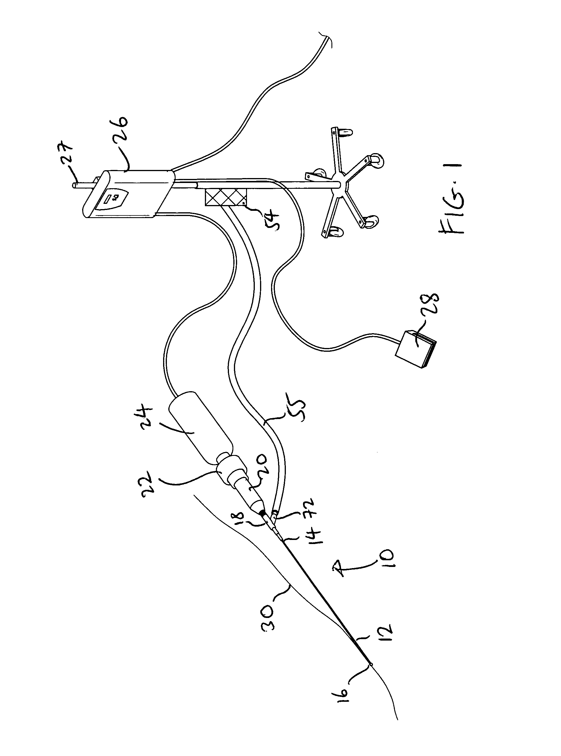
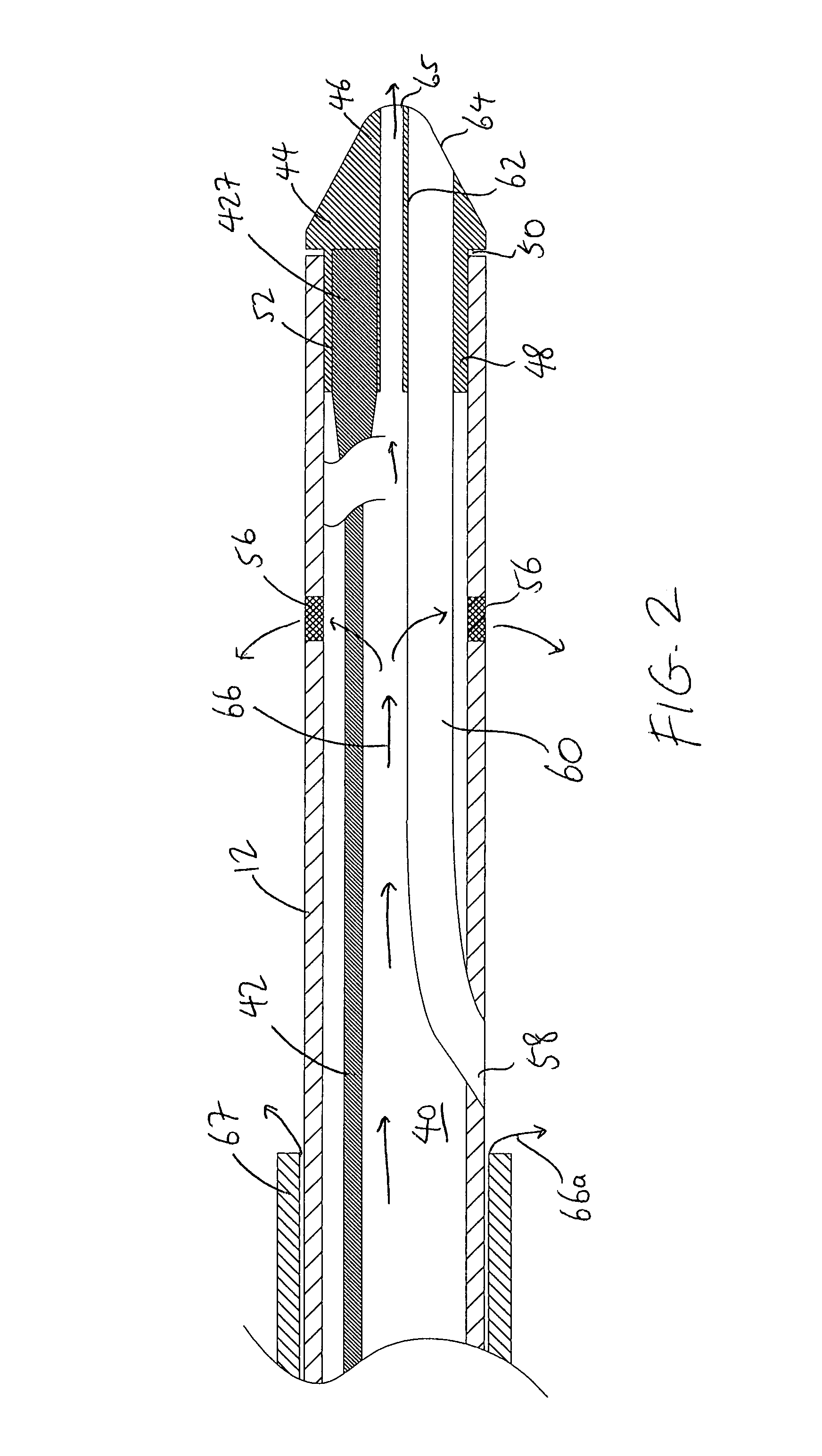
[0023]FIGS. 1 and 2 illustrate an ultrasound system according to the present invention for use in ablating and removing occlusive material inside the vessel of an animal or human being. The ultrasound system includes an ultrasound catheter device 10 which has an elongate catheter body 12 having a proximal end 14, a distal end 16, and defining at least one lumen 40 extending longitudinally therethrough. The ultrasound catheter devic...


PUM


Abstract

An ultrasound system has a catheter including an elongate flexible catheter body having at least one lumen extending longitudinally therethrough. An ultrasound transmission wire extends longitudinally through the lumen of the catheter body, and has a proximal region, a distal region, and an intermediate region between the proximal region and the distal region. A sonic connector is connected to the proximal region of the ultrasound transmission wire, and a distal head is positioned at the distal end of the catheter body and coupled to the distal region of the ultrasound transmission wire. The proximal region of the ultrasound transmission wire has a larger diameter than the intermediate region, the intermediate region is continuously tapered with a progressively decreasing diameter from its proximal end to its distal end, and the distal region has a greater diameter than the distal end of the intermediate region.

Description

BACKGROUND OF THE INVENTION[0001]1. Field of the Invention[0002]The present invention pertains to medical equipment, and more particularly, to a therapeutic ultrasound system for ablating obstructions within tubular anatomical structures such as blood vessels.[0003]2. Description of the Prior Art[0004]A number of ultrasound systems and devices have heretofore been proposed for use in ablating or removing obstructive material from blood vessels. However, all of these systems and devices generally encounter three types of problems which are not always adequately addressed by these systems and devices.[0005]One type of problem relates generally to the effective transmission of ultrasound energy from an ultrasound source to the distal tip of the device where the ultrasound energy is applied to ablate or remove obstructive material. Since the ultrasound source, such as a transducer, is usually located outside the human body, it is necessary to deliver the ultrasound energy over a long di...

Claims


Application Information

Patent Timeline
Patent Type & Authority Patents(United States)
IPC IPC(8): A61B17/32A61B17/22A61B17/00
CPCA61B17/22012A61B2017/00477A61M2025/0183A61B2017/22001A61B2017/22082A61B2217/007
Inventor NITA, HENRY
Owner FLOWCARDIA
Learn More