Eureka AIR delivers breakthrough ideas for toughest innovation challenges, trusted by R&D personnel around the world.

Temporary electrode connection for wireless pacing systems

a wireless pacing and wireless technology, applied in the field of tissue stimulation implantable devices, can solve the problems of limiting the number of heart sites that may be stimulated, removing or repositioning obstacles, and the technique does not translate directly for wireless pacing systems

Active Publication Date: 2016-03-15
EBR SYST
View PDF156 Cites 20 Cited by
  • Summary
  • Abstract
  • Description
  • Claims
  • Application Information

AI Technical Summary

Benefits of technology

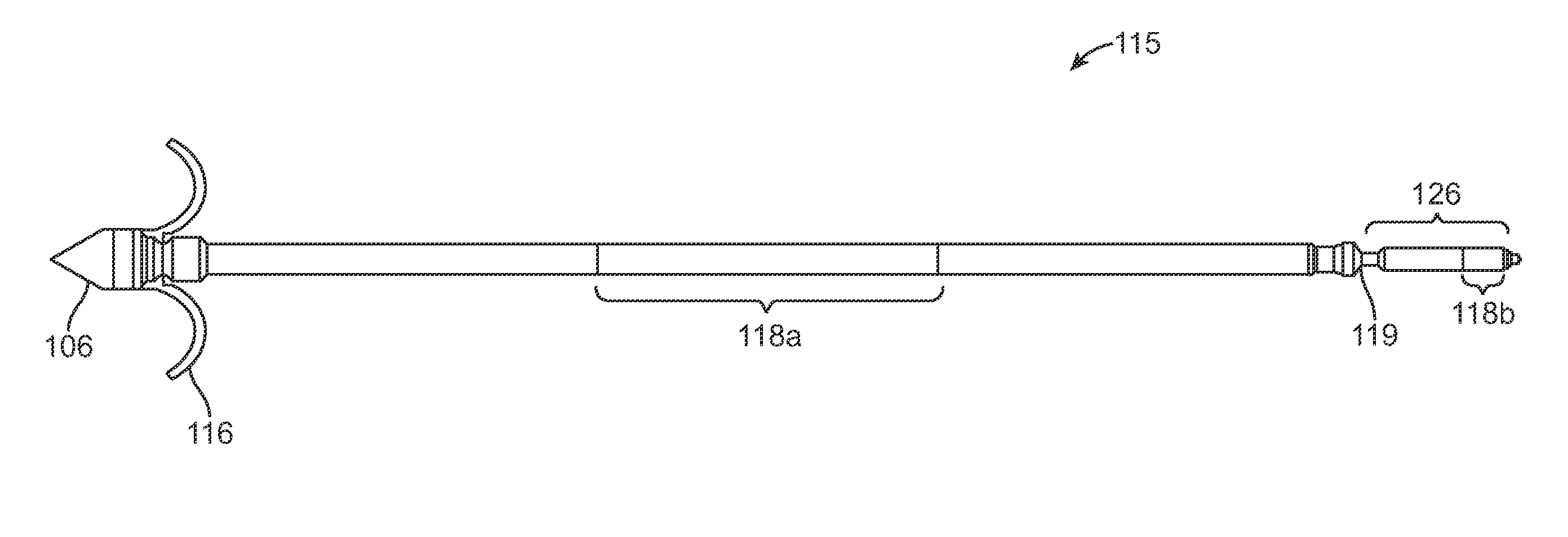
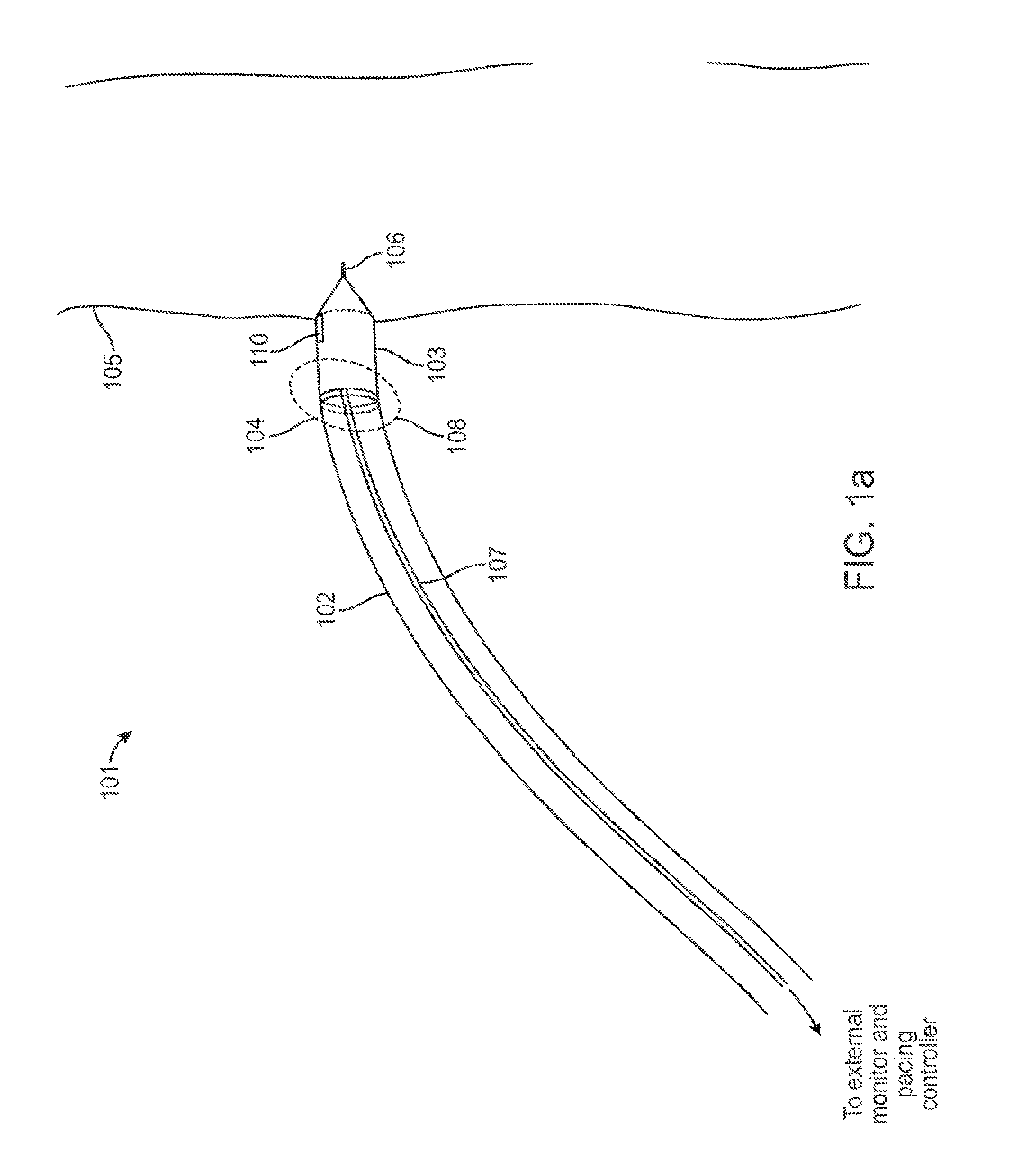
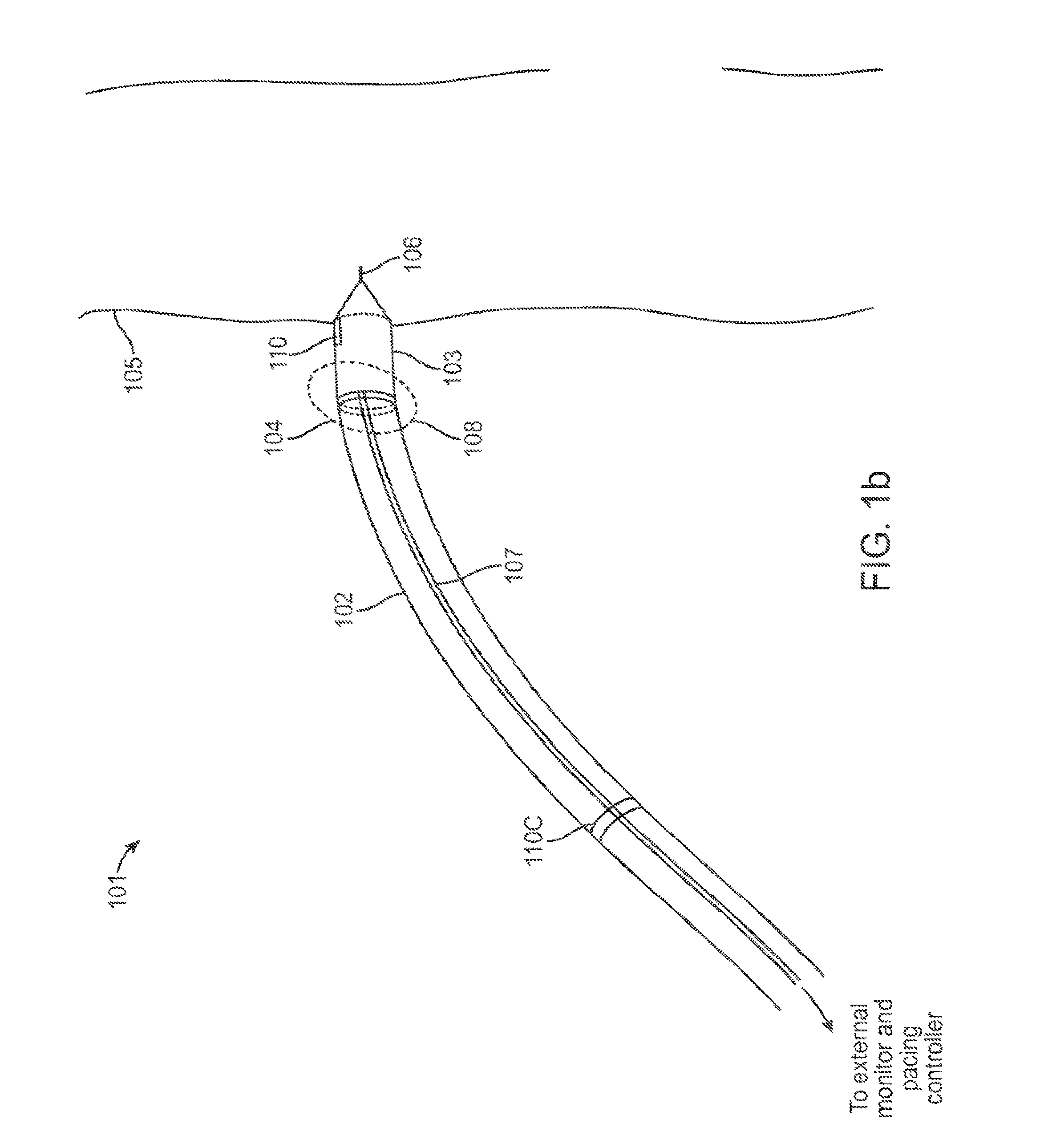
[0018]Once a receiver-stimulator is positioned at a heart location intended as the implant location, the heart tissue is stimulated using electrical stimulation energy from an external pacing controller delivered to the tissue through the receiver-stimulator's cathode and an anode via the temporary electrical connection(s), thereby allowing determination of an acceptable electrical pacing threshold at the location of the cathode prior to permanent attachment of the wireless receiver-stimulator to the heart wall.

Problems solved by technology

For example, the gradual intertwining of leads with heart tissue over time secures the lead in place but also hinders lead removal or repositioning.
Another drawback to using leads is the limit placed on the number of heart sites that may be stimulated.
While the determination of the location in conventional systems with leads involves fairly straightforward techniques, such techniques do not translate directly for wireless pacing systems.
In contrast, in a wireless system one obstacle is the lack of a direct connection to one or more of the electrodes for the monitoring of EGM signals.
This could result in user confusion and potentially inaccurate determination of pacing thresholds and energy conversion efficiencies.
For example, in a conventional pacing system with leads, a high pacing threshold implies a poor location for placing the pacing electrodes.
In contrast, in a wireless system a high energy level that is required to pace could be the result of inefficient or poor wireless transfer of energy from the transmitter to the receiver-stimulator, or, similar to the conventional pacing system, the result of a poor location of the receiver-stimulator not in close proximity to the tissue or over non-excitable tissue.
While this desirable approach may be constructed, it does give rise to a number of challenges.
First, once the wireless electrode is implanted, disconnected from the delivery system, and the delivery system is removed, any conductive material at the severed connection on the wireless implant, remaining exposed after disconnecting the delivery system from the electrode(s), presents a potential alternate electrical path between the implant electrodes and the exposed remains, allowing some or all of the stimulation current to bypass the desired stimulation path and thereby reduce or entirely undermine stimulation effectiveness.

Method used


Image

  • Temporary electrode connection for wireless pacing systems
  • Temporary electrode connection for wireless pacing systems
  • Temporary electrode connection for wireless pacing systems

Examples


Embodiment Construction

[0040]In the following description, for purposes of explanation, numerous specific details are set forth in order to provide a thorough understanding of the invention. It will be apparent, however, to one skilled in the art that the invention can be practiced without these specific details.

[0041]Reference in this specification to “one embodiment” or “an embodiment” means that a particular feature, structure, or characteristic described in connection with the embodiment is included in at least one embodiment. The appearances of the phrase “in one embodiment” in various places in the specification are not necessarily all referring to the same embodiment, nor are separate or alternative embodiments mutually exclusive of other embodiments. Moreover, various features are described which may be exhibited by some embodiments and not by others. Similarly, various requirements are described which may be requirements for some embodiments but not other embodiments. In general, features describ...


PUM


Abstract

Delivery of an implantable wireless receiver-stimulator (R-S) into the heart using delivery catheter is described. R-S comprises a cathode and an anode and wirelessly receives and converts energy, such as acoustic ultrasound energy, to electrical energy to stimulate the heart. Conductive wires routed through the delivery system temporarily connect R-S electrodes to external monitor and pacing controller. R-S comprises a first temporary electrical connection from the catheter to the cathode, and a second temporary electrical connection from the catheter to the anode. Temporary electrical connections allow external monitoring of heart's electrical activity as sensed by R-S electrodes to determine tissue viability for excitation as well as to assess energy conversion efficiency.

Description

CROSS-REFERENCES TO RELATED APPLICATIONS[0001]The present application is a continuation of International Patent Application No. PCT / US2009 / 037978, filed Mar. 23, 2009, which claims the benefit of provisional U.S. Application No. 61 / 039,335, filed Mar. 25, 2008, the full disclosures of which are incorporated herein by reference.BACKGROUND OF THE INVENTION[0002]1. Field of the Invention[0003]The field of the present invention relates generally to implanted devices for tissue stimulation, monitoring, and other therapeutic or diagnostic functions, and specifically to implantable devices for the stimulation of cardiac tissue, for example pacemakers or implantable cardioverter-defibrillators (ICDs). More specifically, it pertains to such devices utilizing wireless energy transfer, for example using ultrasound energy.[0004]2. Description of the Background Art[0005]Pacemakers provide electrical stimulus to heart tissue to cause the heart to contract and hence pump blood. Conventionally, pac...

Claims


Application Information

Patent Timeline
Patent Type & Authority Patents(United States)
IPC IPC(8): A61N1/362A61N1/375A61N1/372A61N1/378A61B17/34A61B5/042
CPCA61N1/362A61N1/3756A61N1/37205A61B5/042A61B17/3468A61N1/3787A61N1/37223A61B5/283A61B5/29A61N1/3702
Inventor MOORE, DAVID F.COWAN, MARK W.WILLIS, N. PARKER
Owner EBR SYST
Why Eureka
Eureka Blog
Learn More