High pressure fluid system

a fluid system and high-pressure technology, applied in the direction of valve housings, liquid fuel engines, machines/engines, etc., can solve the problems of high wear and tear of components of such assemblies or systems, high operating stress and wear of components, and difficult access, so as to reduce manufacturing, assemble and service the effect of less components and fewer components

Active Publication Date: 2016-03-15
PSI PRESSURE SYST
View PDF67 Cites 16 Cited by
  • Summary
  • Abstract
  • Description
  • Claims
  • Application Information

AI Technical Summary

Benefits of technology

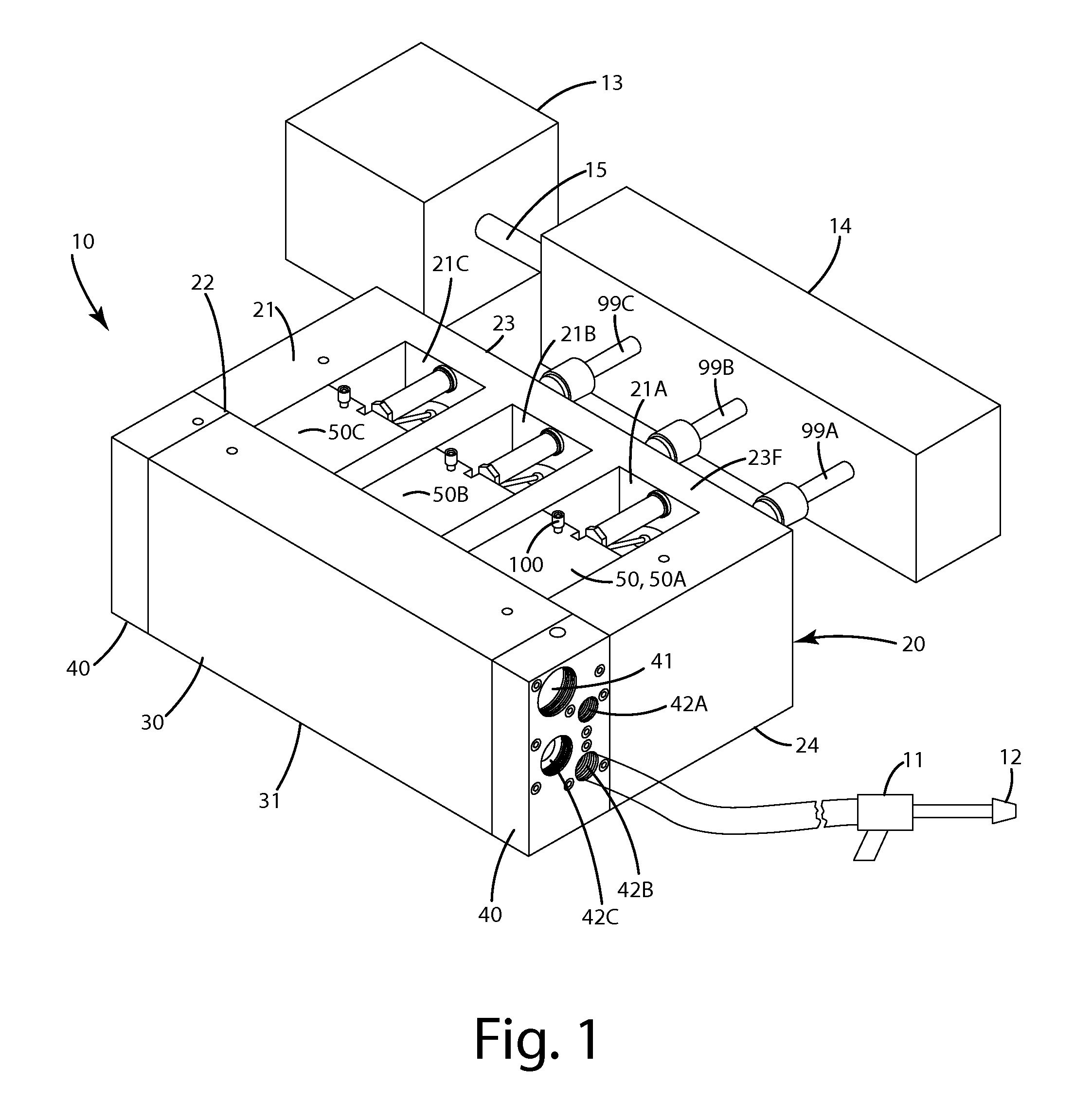
[0015]In still a further embodiment, the fluid end assembly includes a discharge manifold joined with the frame, for example, by fasteners. Optionally, the discharge manifold and frame can be an integral, one piece construction, formed from a continuous piece of material. A discharge manifold end plate can be mounted to the discharge manifold and / or frame. The discharge manifold end plate can include one or more discharge outlets adapted to couple to blasting equipment or other components, so that fluid, such as water, can be conveyed under pressure from the CAM to the discharge manifold and out preselected ones of the discharge outlets. Optionally, the discharge manifold end plate can be removably mounted to the discharge manifold and / or frame so that it can be easily replaced, serviced or otherwise modified without having to remove the entire discharge manifold from the fluid end assembly frame.
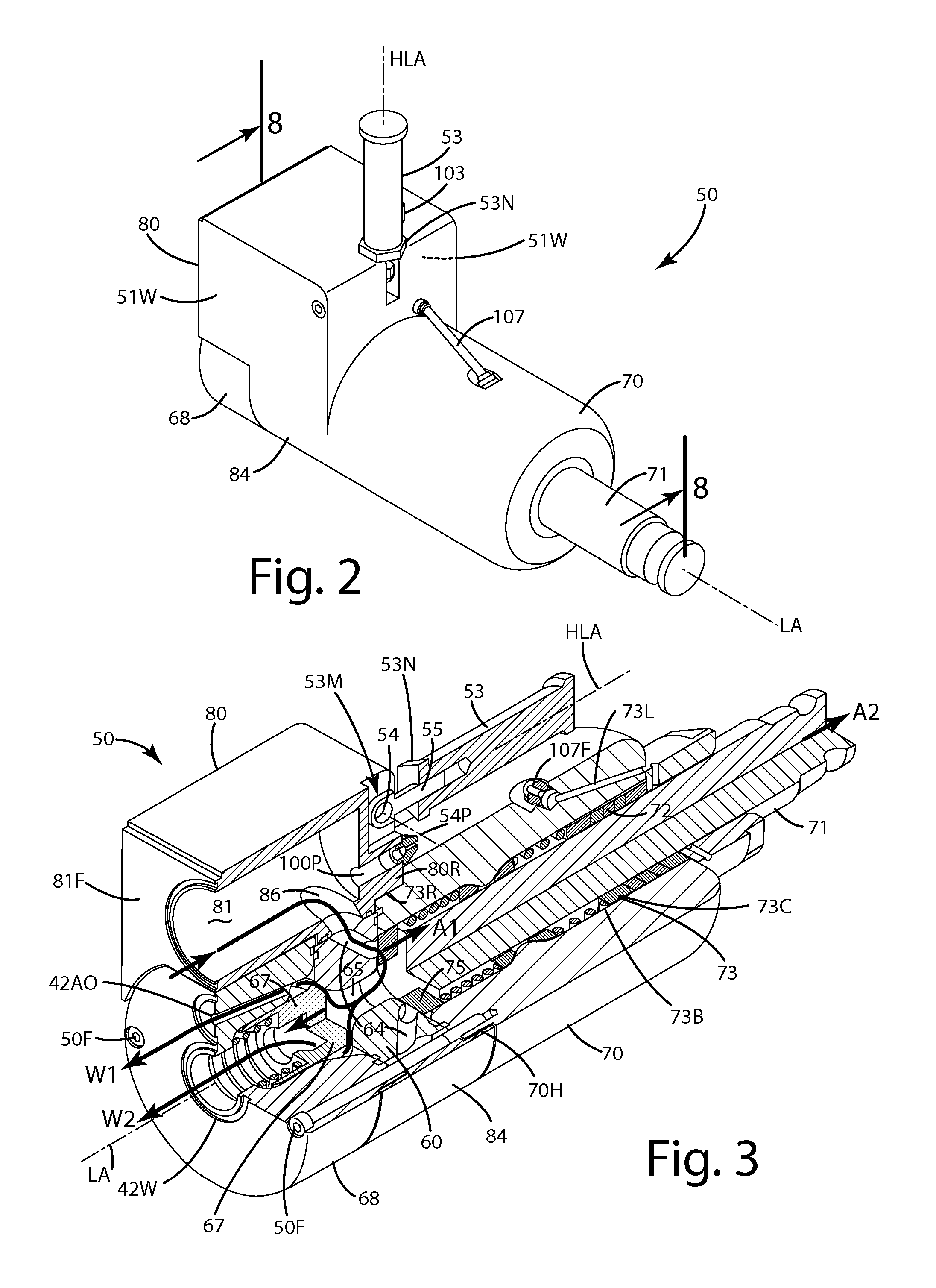
[0032]Where the system includes a lubrication system that uses the pumping fluid to lubricate the packing, it can provide a measured flow of high pressure fluid to the packing in the annular gap between the seal cartridge and the reciprocating plunger. The absence of external plumbing can minimize the likelihood of leakage or damage. By reclaiming the pumping fluid, the lubrication system avoids costs and complexities associated with a separate supply of lubricant or cooling liquids.

Problems solved by technology

Because of the operation between high and low pressures, and the high rate of operation components of the fluid end assembly undergo extreme stress and wear.
Typically, the high wear components of such an assembly or system are mounted deep within a fluid cylinder end, and are hard to access.
This makes replacement and general service of these high wear components difficult and time consuming.
Some service jobs take several hours to a full day, which means that the system is out of commission for extended durations.
This can be very costly, particularly where the system is being used to clean a plant or facility that is off-line while the cleaning takes place.
The manifold itself weighs several hundred pounds, so its handling can be difficult alone.
Thus, the servicing of conventional fluid end assemblies is extremely time consuming and difficult.
As mentioned above, the removable manifolds of fluid end assemblies are large and unwieldy.
They also can present several other issues.
With only one discharge port per manifold, customization is limited, and can require replacement of the entire manifold to provide variability.
Sometimes, the threads can become stripped or damaged due to careless handling or galling, in which case the entire manifold may need to be replaced or the port rethreaded.
This can be extremely costly and time consuming.
If, instead, a rupture disc designed for a 40,000 psi (about 10 gpm) is erroneously used, the system could be over-pressurized and could fail, which could lead to great bodily injury to an operator of the blasting equipment or worse.
During field service of the rupture disc, operator error in selecting the wrong rupture disc is frequently increased due to time, pressure and a sensory overloading environment.
While this is a workable connection, it is time consuming and requires the use of an extra hand tool to service the connection.
The uncoupling and re-coupling of these components is time consuming and can lead to system failure if improperly executed.
While conventional fluid end assemblies offer some level of serviceability and safety, some can fall short, and can present complex operation and servicing issues.

Method used


Image

  • High pressure fluid system
  • High pressure fluid system
  • High pressure fluid system

Examples


first alternative embodiment

[0159]A first alternative embodiment of the high pressure fluid end system with its components is shown in FIGS. 27-41 and generally designated 110. This fluid end is similar and / or identical in structure, function and components to the embodiment described above with several exceptions. For example, the fluid end system 110 includes a frame 120 to which a discharge manifold 130 is joined or monolithically formed therewith. The discharge manifold alternatively can be bolted on with a series of bolts able to withstand the extreme pressures at which the fluid end system operates.

[0160]Like the embodiment above, the fluid end system can 110 be configured for attachment to a drive unit via a transmission and multiple cross head stubs (not shown). The fluid end system 110 also is configured for attachment to blasting equipment 10, for example, a spray gun having a nozzle 12 for shooting liquid at high pressures as shown in FIG. 29. This blasting equipment, as mentioned in the embodiment ...


PUM


Abstract

A high pressure fluid system including enhanced safety, maintenance and servicing features. The system can include a CAM assembly module, having a valve seat assembly, seal cartridge assembly and inlet manifold, that is easily installed in and removed from a frame and / discharge manifold as a single unit. A discharge manifold can isolate different pressure rated passageways of the system, and multiple rupture discs associated with the same. A discharge manifold end plate can be included to provide ease of repair of discharge outlets and to establish a plumbing system for the rupture discs. A quick coupler can facilitate connection between a plunger of the seal cartridge assembly and a cross head stub connected to a power frame. A lubrication valve assembly can provide and meter lubrication from a high pressure inlet source to a plunger and packing of the seal cartridge assembly.

Description

BACKGROUND OF THE INVENTION[0001]The present invention relates to a high pressure fluid system and more particularly to advancements in the safety, maintenance and servicing of the same.[0002]High pressure fluid jetting systems are used in a variety of fluid jetting operations, such as cleaning, pipe clearing, cutting, removal of debris and coating, to name a few. Most such systems include a fluid end assembly, a drive assembly, a pressurized liquid supply and water blasting equipment, such as a spray gun. The drive assembly usually is in the form of an engine or motor coupled to a drive shaft that drives multiple plungers in a reciprocating manner within a fluid cylinder end. The multiple plungers force fluid, such as water, out of the spray gun at extremely high pressure. As the plungers reciprocate, the fluid cylinder assembly and its components cycle at an extremely high rate and fluctuate between atmospheric and maximum system pressure.[0003]Because of the operation between hig...

Claims


Application Information

Patent Timeline
Patent Type & Authority Patents(United States)
IPC IPC(8): F16K5/22F04B53/22F04B53/18F16K43/00B05B9/04F04B53/16B24C7/00F16K27/00
CPCF16K5/22B05B9/0413B24C7/0015F04B53/16F04B53/164F04B53/18F04B53/22F16K27/003F16K43/00Y10T137/4238Y10T137/6011Y10T137/877F16K13/04F16K17/16
Inventor FORREST, JAMIE A.SHAWVER, TODD A.
Owner PSI PRESSURE SYST
Why Eureka
Try Eureka