
Production apparatus for manufacturing sensor package structure

a production apparatus and sensor technology, applied in electrical apparatus, semiconductor devices, radio frequency controlled devices, etc., can solve the problems of inability to control the flow of adhesive, the die fixed on the glass by the csp process needs to spend too much time to reduce the capacity of the package structure, and the cost of the sensor package structure. , to achieve the effect of increasing the capacity and yield reducing the cost of the sensor package structur

Active Publication Date: 2016-03-15
AZUREWAVE TEHNOLOGIES INC
View PDF2 Cites 0 Cited by
  • Summary
  • Abstract
  • Description
  • Claims
  • Application Information

AI Technical Summary

Benefits of technology

The patent describes a sensor package structure and a production apparatus for making it. This structure uses a pressure-sensitive adhesive sheet to stick a light-filtering sheet and a sensing die together, increasing the capacity of the package. The pressure-sensitive adhesive sheet is solid and easy to install, and the light-filtering sheet helps keep the sensing die flat for better yields. The sensing region of the sensing die is sealed to prevent particle pollution when installing it to other components. The production apparatus helps make the sensor package structure faster and cheaper by using a small clean room and reducing production costs.

Problems solved by technology

Specifically, after dripping the adhesive (e.g., epoxy resin or silicone) in-between the glass and the die, the adhesive needs a lot of time to solidify by baking.
Thus, the die fixed on the glass by the CSP process needs to spend too much time to reduce the capacity of the package structure.
However, during the said pressing, the adhesive (e.g., epoxy resin or silicone) is pressed to flow radially, and the flow of the adhesive cannot be controlled.
Specifically, when the pressing distribution is not uniform, the glass easily has a tilt to the die for generating a package structure problem, which is the glass non-parallel to the die.
Additionally, when the package structure is formed by the COB process, the die is directly combined to the circuit board by wiring, and the package structure formed by the COB process does not have any glass to protect the die, so that the die has a particle pollution problem installing the package structure to the other components (e.g., lens).

Method used


Image

  • Production apparatus for manufacturing sensor package structure
  • Production apparatus for manufacturing sensor package structure
  • Production apparatus for manufacturing sensor package structure

Examples


first embodiment

[First Embodiment]

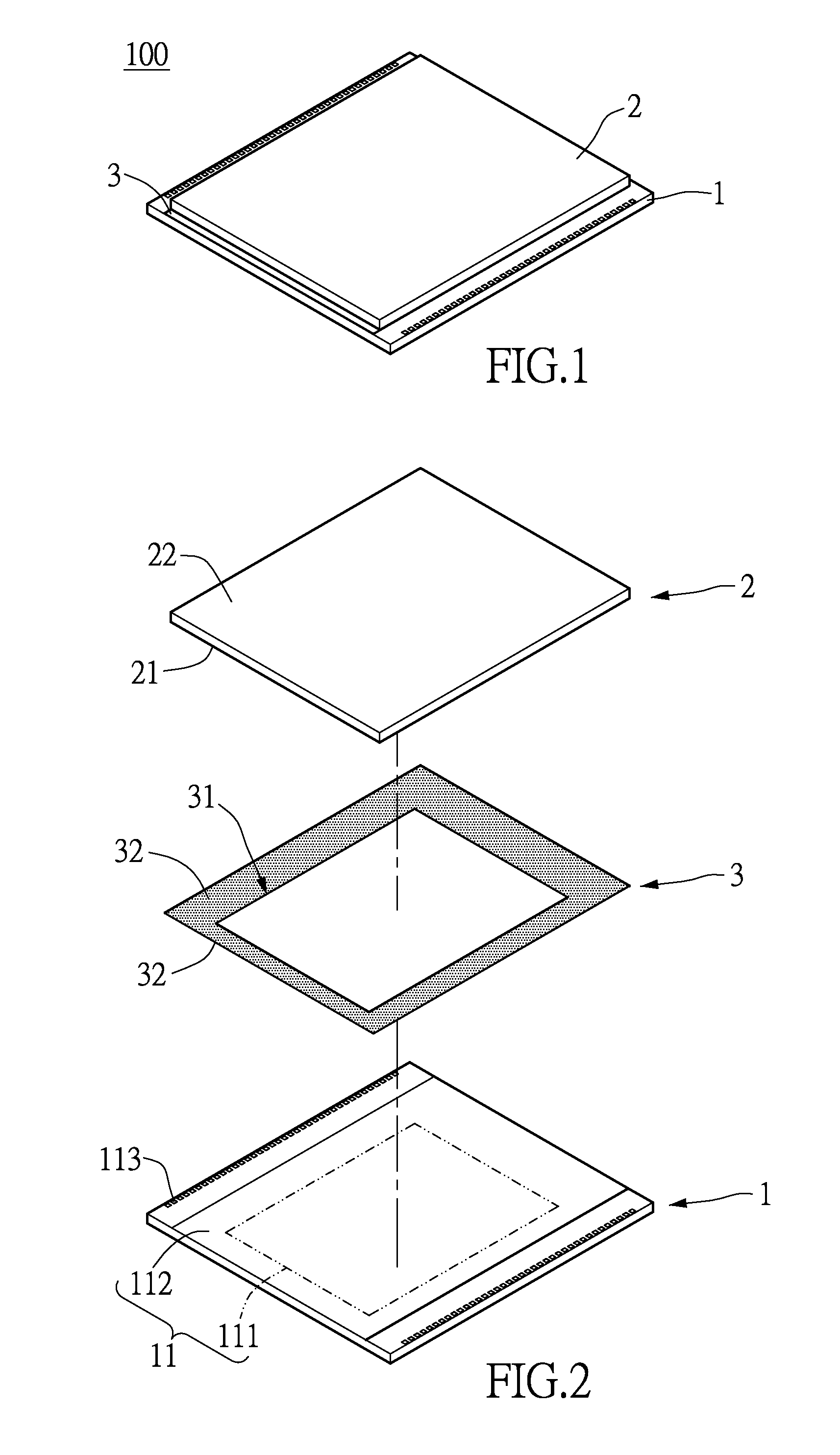
[0024]Please refer to FIGS. 1 and 2, which show a first embodiment of the instant disclosure. The instant embodiment provides a sensor package structure 100 including a sensing die 1, a light-filtering sheet 2, and a pressure-sensitive adhesive sheet 3, which has a rectangular annular shape. The following description discloses the detail construction of the sensing die 1, the light-filtering sheet 2, and the pressure-sensitive adhesive sheet 3 firstly, and then discloses the connecting relationship between the components of the sensor package structure 100.

[0025]The sensing die 1 in the instant embodiment takes a rectangular image sensing die for example. The sensing die 1 includes an active surface 11. The active surface 11 has a sensing region 111 and an annular connecting region 112 surrounding around the sensing region 111. The sensing die 1 includes a plurality of pads 113 respectively exposed from two opposite portions of the connecting region 112 (i.e., the ...

second embodiment

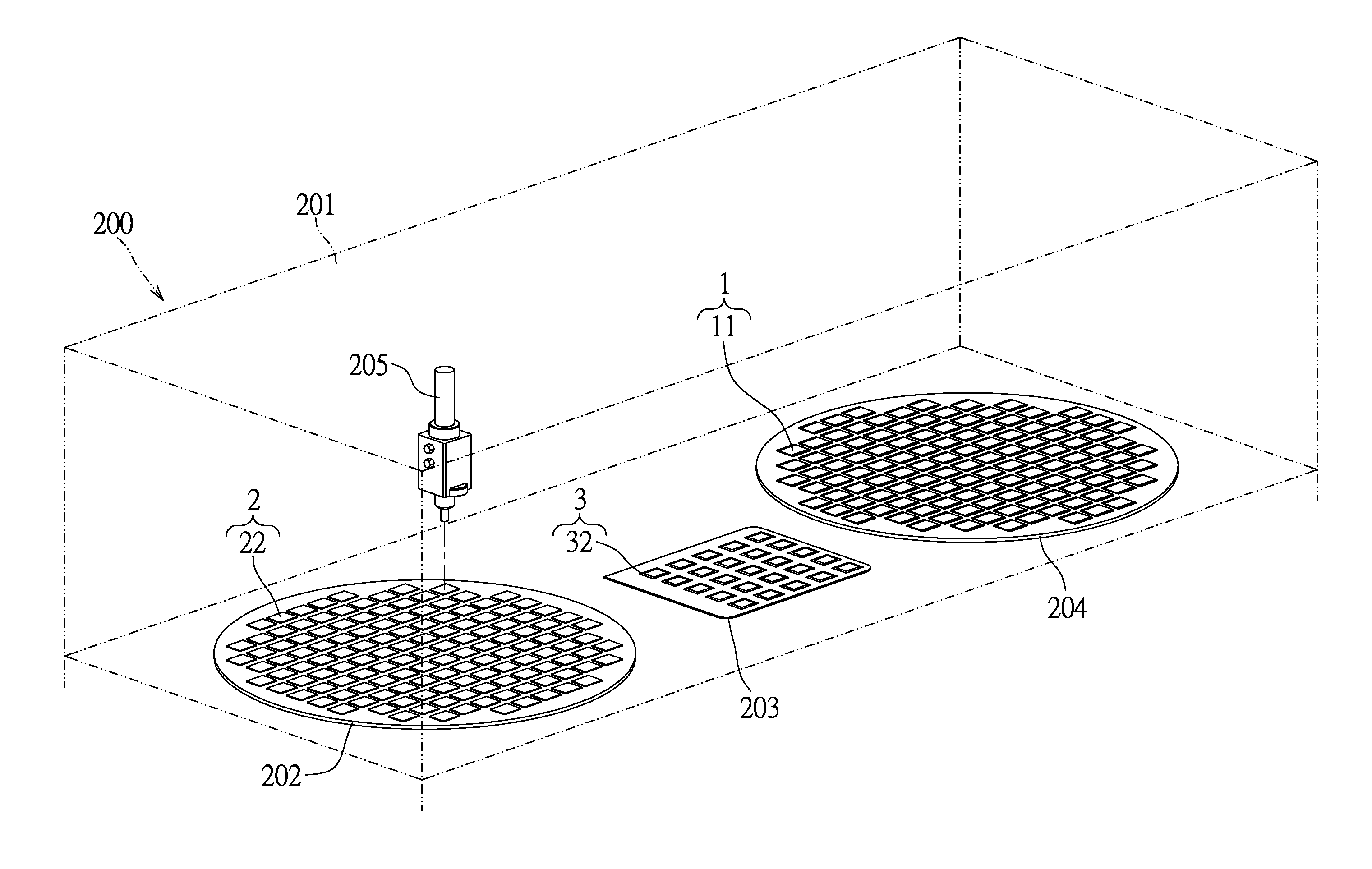
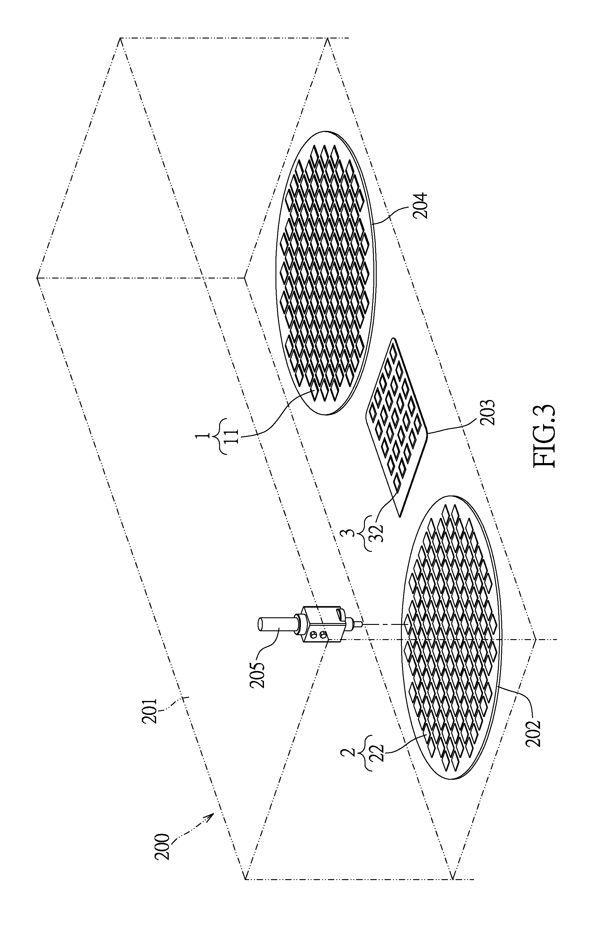
[Second Embodiment]

[0038]Please refer to FIGS. 3 through 10, which show a second embodiment of the instant disclosure. The second embodiment provides a production apparatus 200 used for manufacturing the sensor package structure 100 disclosed in the first embodiment. The sensor package structure 100 has been disclosed in the first embodiment, so that the instant embodiment does not state the construction of the sensor package structure 100 again.

[0039]The production apparatus 200 includes a machine body 201, a first workbench 202, a second workbench 203, a third workbench 204, and a shifting member 205. The first workbench 202, the second workbench 203, the third workbench 204, and the shifting member 205 are installed on the machine body 201, and the machine body 201 includes a driving module (not shown) for providing the three dimensional movement of the shifting member 205. The driving module is a conventional feature, so the instant embodiment does not state in detail.

[0040]The ...


PUM

PropertyMeasurementUnit
pressure-sensitiveaaaaaaaaaa
pressure-aaaaaaaaaa
thicknessaaaaaaaaaa

Abstract

A sensor package structure includes a sensing die, a light-filtering sheet, and an annular pressure-sensitive adhesive sheet. An active surface of the sensing die has a sensing region and a connecting region around the sensing region. The periphery contour of sensing die is greater than or equal to the periphery contour of light-filtering sheet. The pressure-sensitive adhesive sheet has two opposite adhesive surfaces and defines an opening. The adhesive surfaces respectively adhere to the connecting region of the sensing die and the inner surface of the light-filtering sheet, and the sensing region faces the inner surface of the light-filtering sheet via the opening. The sensing region is sealed by the pressure-sensitive adhesive sheet and the light-filtering sheet. Thus, the instant disclosure provides the sensor package structure with low cost, high capacity, and high yield. Moreover, the instant disclosure provides a production apparatus for manufacturing the sensor package structure.

Description

BACKGROUND OF THE INVENTION[0001]1. Field of the Invention[0002]The instant disclosure relates to a package structure; more particularly, to a production apparatus for manufacturing a sensor package structure.[0003]2. Description of Related Art[0004]The conventional compact camera module (CCM) is almost produced by the chip scale package (CSP) process or the chip on board (COB) process. When the package structure is formed by the CSP process, a glass and a die are fixed to each other via an adhesive (e.g., epoxy resin or silicone). Specifically, after dripping the adhesive (e.g., epoxy resin or silicone) in-between the glass and the die, the adhesive needs a lot of time to solidify by baking. Thus, the die fixed on the glass by the CSP process needs to spend too much time to reduce the capacity of the package structure.[0005]Moreover, the dripping step of the package structure is implemented by utilizing the dripping machine, and then combining the glass and the die with each other ...

Claims


Application Information

Patent Timeline
Patent Type & Authority Patents(United States)
IPC IPC(8): H01L27/146
CPCH01L27/14618Y10T29/53
Inventor HSU, CHI-HSINGLIU, CHING-WEILU, CHUN-YU
Owner AZUREWAVE TEHNOLOGIES INC
Learn More