Stator teeth, stator, rotating electric machine, and method for controlling rotating electric machine

a technology of stators and electric machines, applied in the direction of motor/generator/converter stoppers, dynamo-electric converter control, magnetic circuit shape/form/construction, etc., can solve the problems of weakened magnetic flux of magnets, inability to apply electric current through coils,

Inactive Publication Date: 2016-03-15
SHIBAURA INST OF TECH
View PDF69 Cites 18 Cited by
  • Summary
  • Abstract
  • Description
  • Claims
  • Application Information

AI Technical Summary

Benefits of technology

[0023]According to the stator teeth of the first aspect, the stator of the second aspect, the rotating electric machine of the third aspect, and the method for controlling the rotating electric machine of the fourth aspect, by switching the switches, the connection state of winding units wound around the stator teeth is changed between the concentrated winding state and the distributed winding state depending on the rotating speed. Thereby, without making a device larger, it is possible to perform plural driving characteristics and expand output range with just a single motor.
[0026]According to the sixth aspect, it is not necessary to connect an inverter outside. Thereby, it is possible to realize downsizing of the system.
[0028]According to the seventh aspect, it is possible to reduce the torque ripple so as to reduce the iron loss,
[0030]According to the controlling method of the eighth aspect, it is possible to dissolve unbalance between phases by equalizing the number of coils of rotor side and the number of coils of yoke side to each other.
[0036]According to the twelfth aspect, at a moment when the current of each phase has become zero, the connection state is switched between the first connection state and the second connection state. Accordingly, the torque triple does not occur. Further, as the voltage spike does not occur at a moment of switching, it is possible to switch the connection state of winding units without loss.

Problems solved by technology

Because of this, when the induced voltage becomes higher than the voltage of the inverter, it is impossible to apply the electric current through the coils.
When using the field-weakening control, the magnetic flux of the magnets looks weakened.

Method used


Image

  • Stator teeth, stator, rotating electric machine, and method for controlling rotating electric machine
  • Stator teeth, stator, rotating electric machine, and method for controlling rotating electric machine
  • Stator teeth, stator, rotating electric machine, and method for controlling rotating electric machine

Examples


first embodiment

[0078][The First Embodiment]

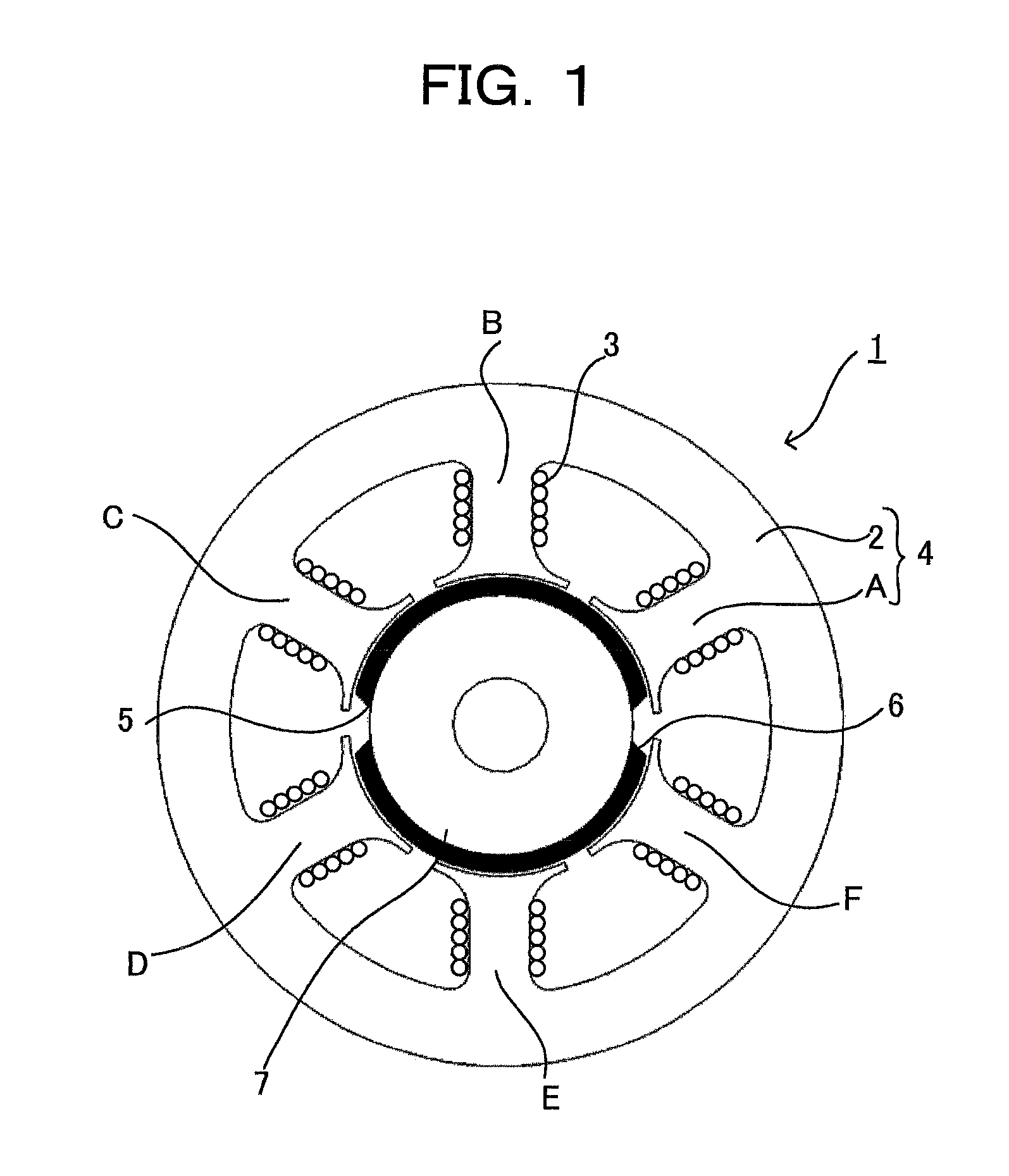
[0079]FIG. 1 shows a construction of a permanent magnet synchronous motor with two poles (a pair of poles) and six slots (the number of stator teeth: six) of the first embodiment of the present invention. As shown in FIG. 1, the permanent magnet synchronous motor 1 has a stator 4 which comprises: a stator yoke 2 made of silicon steel sheet or the like; and six pieces of stator teeth A, B, C, D, E, and F which are also made of silicon steel sheet so as to be formed integrally with the stator yoke 2 or formed in a fixable manner to the stator yoke 2. And, inside the six pieces of the stator teeth A, B, C, D, E and F, a rotor 7 is provided in a rotatable manner, the rotor 7 having permanent magnets with N pole 5 and S pole 6 in the outer circumference portion of the rotor 7.

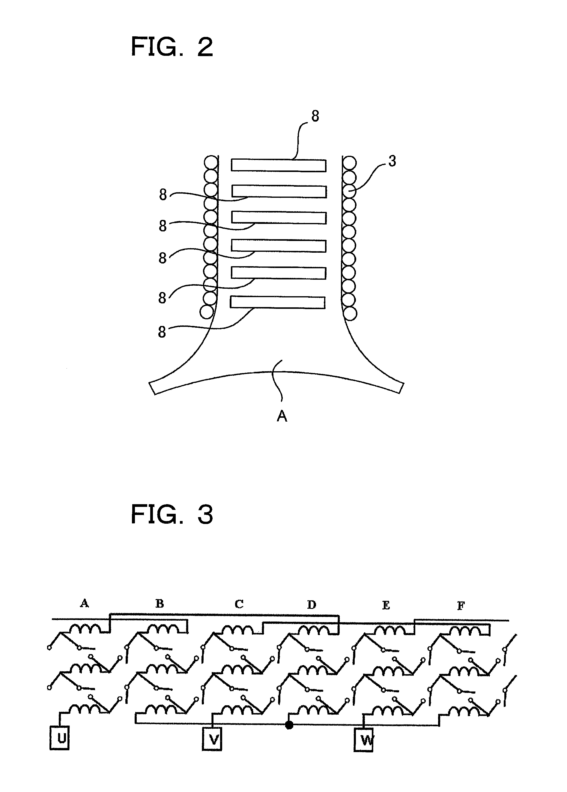
[0080]Around each of the six pieces of stator teeth A to F, three coils 3 are wound. FIG. 2 is a diagram showing a construction of one single stator tooth A. As shown in FIG. 2, to one si...

second embodiment

[0098]The Second Embodiment

[0099]FIG. 12 is a connection diagram of concentrated winding coils connected in parallel in the second embodiment of the present invention. As one example, the connection state of only the U phase is shown. In this example, the switches 8 are provided to both end portions of three coils 3 of each of the stator teeth A to F, and all of the both end portions of the three coils 3 are connected. As a result of that, the coils 3 become a state of concentrated winding coils connected in parallel.

[0100]In a case that the state of coils 3 is made into the concentrated winding coils connected in parallel in this way, as the induced voltage becomes one sixth in comparison with a case of concentrated winding coils connected in series shown in FIG. 4, driving with further higher speed is possible. The current to be applied to a coil is determined depending on a diameter of the coil. However, in this case, as it is possible to apply current six times as much as the ca...

third embodiment

[0102][The Third Embodiment]

[0103]FIG. 13 shows a construction of a three-phase inverter for motor driving, and

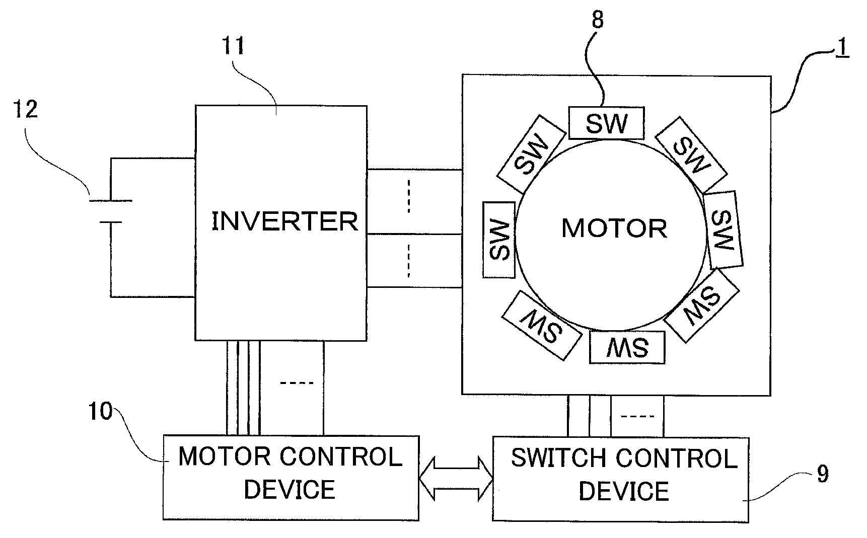
[0104]FIG. 14 shows switching patterns of a 120-degree current supply system as a simple example of driving the inverter shown in FIG. 13. In the third embodiment of the present invention is, as shown in FIG. 15, functions of the inverter are realized by turning on and off the switches 8 without providing the inverter to the outer portion of the motor 1.

[0105]Specifically, as shown in FIG. 16, one end of phase U consisting of a third coil 3 of the stator tooth A, a second coil 3 of the stator tooth B, and a first coil 3 of the stator tooth C is connected with a plus terminal. The other end of the first coil of the stator tooth C is connected with a neutral point. Further, one end of the phase V consisting of a third coil 3 of the stator tooth E, a second coil 3 of the stator tooth F, and a first coil 3 of the stator tooth A is connected with a minus terminal.

[0106]In this c...


PUM


Abstract

There is provided a single motor which performs plural driving characteristics and can expand output range thereof. Three coils are wounded around each of the stator teeth A to F, and provided to each stator tooth A to F are switches for providing a concentrated winding state by connecting the three coils in series in each stator tooth A to F, and switches for providing a distributed winding state by connecting in series the coils of any one of units through the stator teeth A to F Depending on the rotating speed, the torque or the like, the coils are changed between the concentrated winding state and the distributed winding state.

Description

CROSS-REFERENCE TO RELATED PATENT APPLICATIONS[0001]This application is a U.S. National Phase Application under 35 U.S.C. §371 of International Patent Application No. PCT / JP2012 / 051895, filed Jan. 27, 2012, and claims the benefit of Japanese Patent Application No. 2011-015774, filed Jan. 27, 2011, all of which are incorporated by reference herein in their entities. The International Application was published in Japanese on Aug. 2, 2012 as International Publication No. WO / 2012 / 102400 under PCT Article 21(2).FIELD OF THE INVENTION[0002]The present invention relates to stator teeth, a stator, a rotating electric machine having the stator, and method for controlling the rotating electric machine.BACKGROUND OF THE INVENTION[0003]A permanent magnet synchronous motor, as using permanent magnets as a rotor thereof, can provide high output and high efficiency in comparison with an induction machine and other motors. As a stator, punched out silicon steel sheets are used in a laminated manner...

Claims


Application Information

Patent Timeline
Patent Type & Authority Patents(United States)
IPC IPC(8): H02P1/00H02P3/00H02P29/00H02P4/00H02P25/18H02K21/16H02K3/20H02K3/28H02P5/00
CPCH02K3/28H02K3/20H02K21/16H02P4/00H02P25/18H02P29/00H02K1/14H02P27/16
Inventor AKATSU, KANHIJIKATA, HIROKI
Owner SHIBAURA INST OF TECH
Why Eureka
Try Eureka