Electrical power control of a field emission lighting system

a field emission and lighting technology, applied in the direction of electric discharge lamps, discharge tubes/lamp details, electric discharge lamps, etc., can solve the problems of complex and expensive recycling of florescent light sources, and achieve the effect of reducing reducing lighting costs, and increasing the lifetime of field emission lighting arrangements

Active Publication Date: 2016-03-15
PUREFIZE TECH AB
View PDF10 Cites 6 Cited by
  • Summary
  • Abstract
  • Description
  • Claims
  • Application Information

AI Technical Summary

Benefits of technology

[0007]Prior art field emission lighting arrangements are generally configured such that, during operation, the cathode emits electrons, which are accelerated toward the complete phosphor layer of the field emission lighting arrangement. The phosphor layer may provide luminescence when the emitted electrons collide with phosphor particles. The luminescence process is accompanied by the production of heat which may reduce the lifetime of the field emission lighting arrangement.
[0008]As a comparison and according to the invention, the field emission lighting arrangements is configured such that instead accelerating electrons towards the complete phosphor layer only selected portions of the phosphor layer are sequentially active to emit light, thereby for example allowing the selected portions of the anode layer to cool down before they are again activated. An advantage with the invention is thus that the lifetime of the field emission lighting arrangement may be increased, thereby possibly also reducing the lighting cost for the end user as the field emission lighting arrangement can be replaced at a lower rate.
[0015]As stated above, the field emission lighting system comprises a first and a second light source and is configured such that each of the first and the second light source is sequentially activated for emitting light. As discussed and indicated above, by only activating one light source only a part of a total time it may be possible to increase the lifetime of the field emission lighting system as well as taking into account the positive effect of the emission decay of a phosphor layer of each of the field emission light sources, thereby possibly also reducing the lighting cost for the end user as the field emission lighting system can be replaced at a lower rate. The field emission lighting system may of course comprise more than two field emission light sources, possibly sequentially activated each at a time or a plurality at a time.

Problems solved by technology

As is well known, all florescent light sources contain a small amount of mercury, posing problems due to the health effects of mercury exposure.
Additionally, due to heavy regulation of the disposal of mercury, the recycling of florescent light sources becomes complex and expensive.

Method used


Image

  • Electrical power control of a field emission lighting system
  • Electrical power control of a field emission lighting system
  • Electrical power control of a field emission lighting system

Examples


Embodiment Construction

[0025]The present invention will now be described more fully hereinafter with reference to the accompanying drawings, in which currently preferred embodiments of the invention are shown. This invention may, however, be embodied in many different forms and should not be construed as limited to the embodiments set forth herein; rather, these embodiments are provided for thoroughness and completeness, and fully convey the scope of the invention to the skilled addressee. Like reference characters refer to like elements throughout.

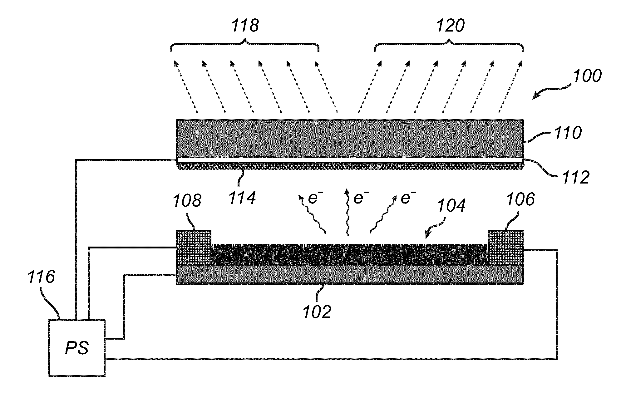
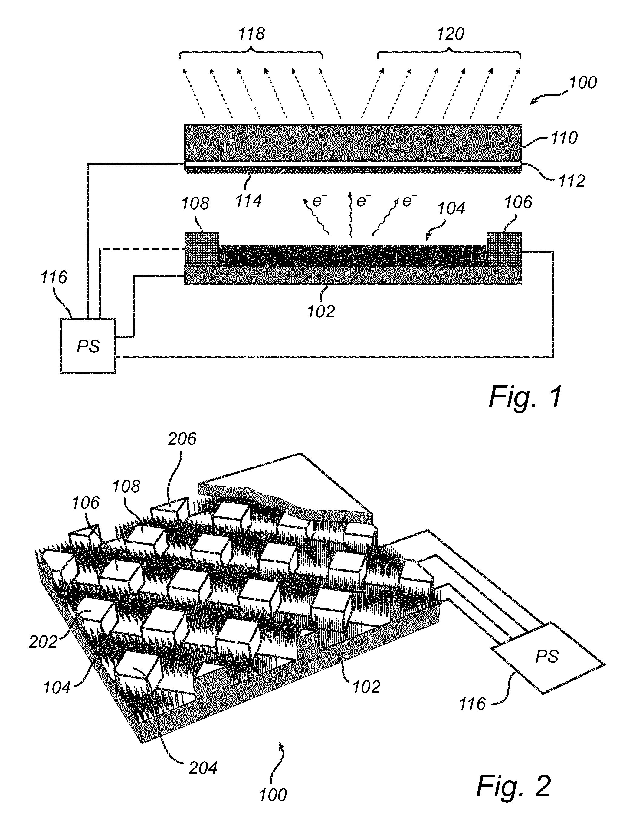
[0026]Referring now to the drawings and to FIG. 1 in particular, there is depicted a side view of a field emission lighting arrangement 100 according to a currently preferred embodiment of the invention. The field emission lighting arrangement 100 comprises a substrate 102 onto which a plurality of sharp emitters has been provided, forming a field emission cathode 104. The sharp emitters may for example comprise ZnO nanostructures, including for example nano wa...


PUM


Abstract

The present invention relates to a field emission lighting arrangement, comprising an anode structure at least partly covered by a phosphor layer, an evacuated envelope inside of which an anode structure is arranged, and a field emission cathode, wherein the field emission lighting arrangement is configured to receive a drive signal for powering the field emission lighting arrangement and to sequentially activate selected portions of the phosphor layer for emitting light. The same control regime may be applied to an arrangement comprising a plurality of field emission cathodes and a single field emission anode. Advantages with the invention includes increase lifetime of the field emission lighting arrangement.

Description

CROSS-REFERENCE TO RELATED APPLICATIONS[0001]This application is a 371 U.S. National Stage of International Application No. PCT / EP2011 / 072060, filed Dec. 7, 2011, which claims priority to EPC No. 10197168.7, filed Dec. 28, 2010. The disclosure of each of the above applications is incorporated herein by reference in their entirety.TECHNICAL FIELD[0002]The present invention relates to a field emission lighting arrangement. More specifically, the invention relates to a field emission lighting arrangement where selected portions of a phosphor layer are sequentially activated for emitting light. The invention also relates to a corresponding field emission lighting system.BACKGROUND OF THE INVENTION[0003]There is currently a trend in replacing the traditional light bulb with more energy efficient alternatives. Florescent light sources also in forms resembling the traditional light bulb have been shown and are often referred to as compact fluorescent lamps (CFLs). As is well known, all flo...

Claims


Application Information

Patent Timeline
Patent Type & Authority Patents(United States)
IPC IPC(8): H01J31/12H01J1/304H05B41/36H01J61/52H01J63/06H01J63/04H01J63/02
CPCH05B41/36H01J1/304H01J61/523H01J63/02H01J63/04H01J63/06
Inventor HU, QIU-HONG
Owner PUREFIZE TECH AB
Why Eureka
Try Eureka