Moving body system and method for controlling travel of moving body

a moving body and moving body technology, applied in the direction of non-mechanical conveyors, railway signalling and safety, instruments, etc., can solve the problem of difficult conversion of the position shifted from the center of control to the position, and achieve the effect of accurately deriving the position and high precision

Active Publication Date: 2016-03-22
MURATA MASCH LTD
View PDF12 Cites 14 Cited by
  • Summary
  • Abstract
  • Description
  • Claims
  • Application Information

AI Technical Summary

Benefits of technology

[0007]Preferred embodiments of the present invention enable a moving body to travel with high precision by accurately deriving the position of the moving body in a curved section.
[0010]Wobbling of the moving body in the curved section makes it difficult to convert positions shifted from the center of control to the positions of the center of control by correcting the ratio of the radii of curvature. Also, when the radius of curvature is made larger at the entrance and exit of the curved section than at other portions, the ratio of the radii of curvature is not constant to begin with. However, in a preferred embodiment of the present invention, a storage unit that stores the positions of the center of control in the travel direction relative to the outputs of the detector for at least the curved section of the travel route of the moving body is provided, and the travel of the moving body is controlled on the basis of the positions of the center of control read out from the storage unit. Accordingly, the detected positions are accurately converted to the position of the center of control, thus enabling the travel to be controlled with high precision even in the curved section. The moving body can also be accurately stopped in the curved section. Note that, herein, description relating to the moving body system also applies directly to the moving body travel control method.

Problems solved by technology

Wobbling of the moving body in the curved section makes it difficult to convert positions shifted from the center of control to the positions of the center of control by correcting the ratio of the radii of curvature.

Method used


Image

  • Moving body system and method for controlling travel of moving body
  • Moving body system and method for controlling travel of moving body
  • Moving body system and method for controlling travel of moving body

Examples


Embodiment Construction

[0021]The following describes preferred embodiments of the present invention. The scope of the present invention is based on the claims, and is intended to be determined in accordance with the understanding of a person skilled in the art with reference to the description of the present invention and related art in the field of the present invention.

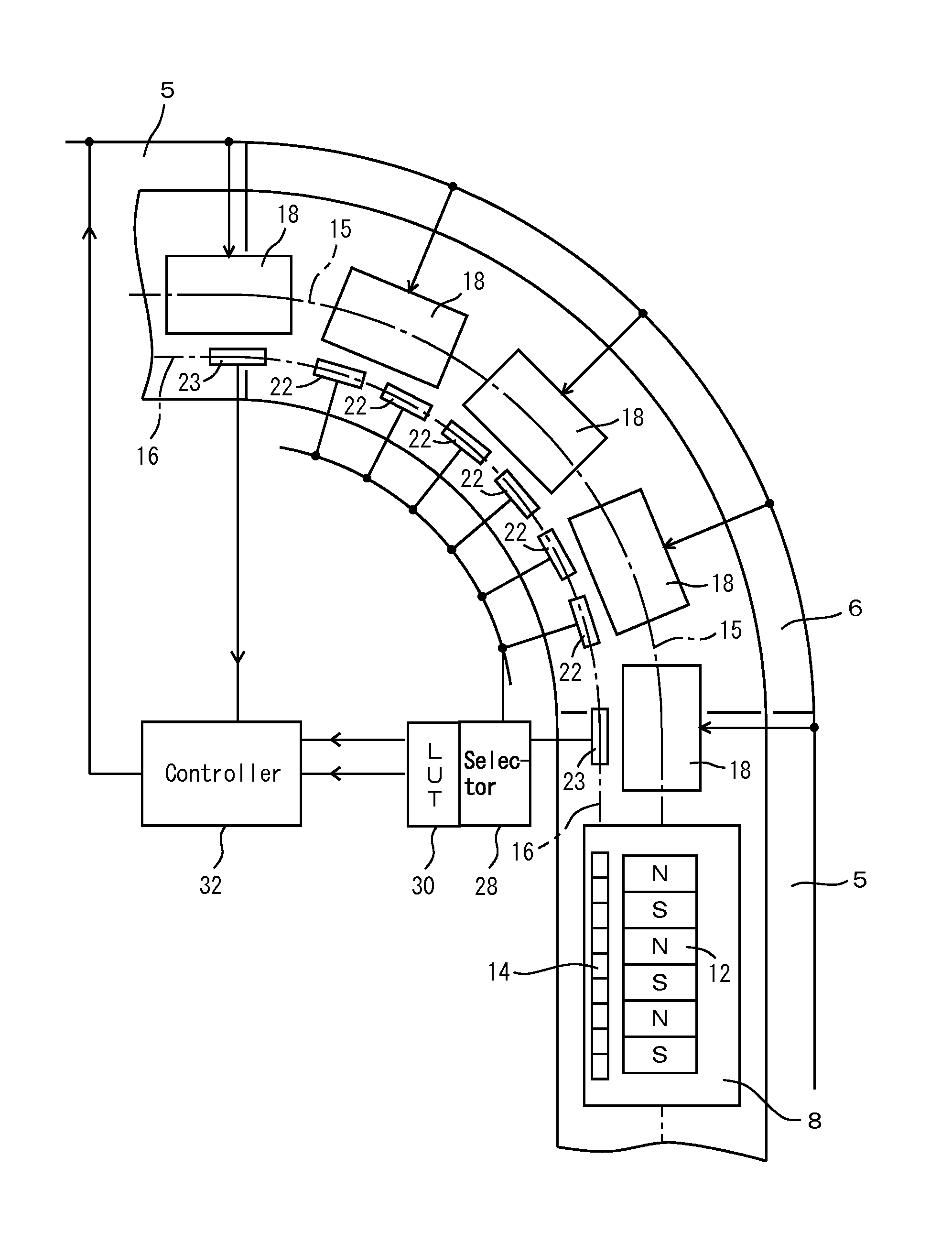
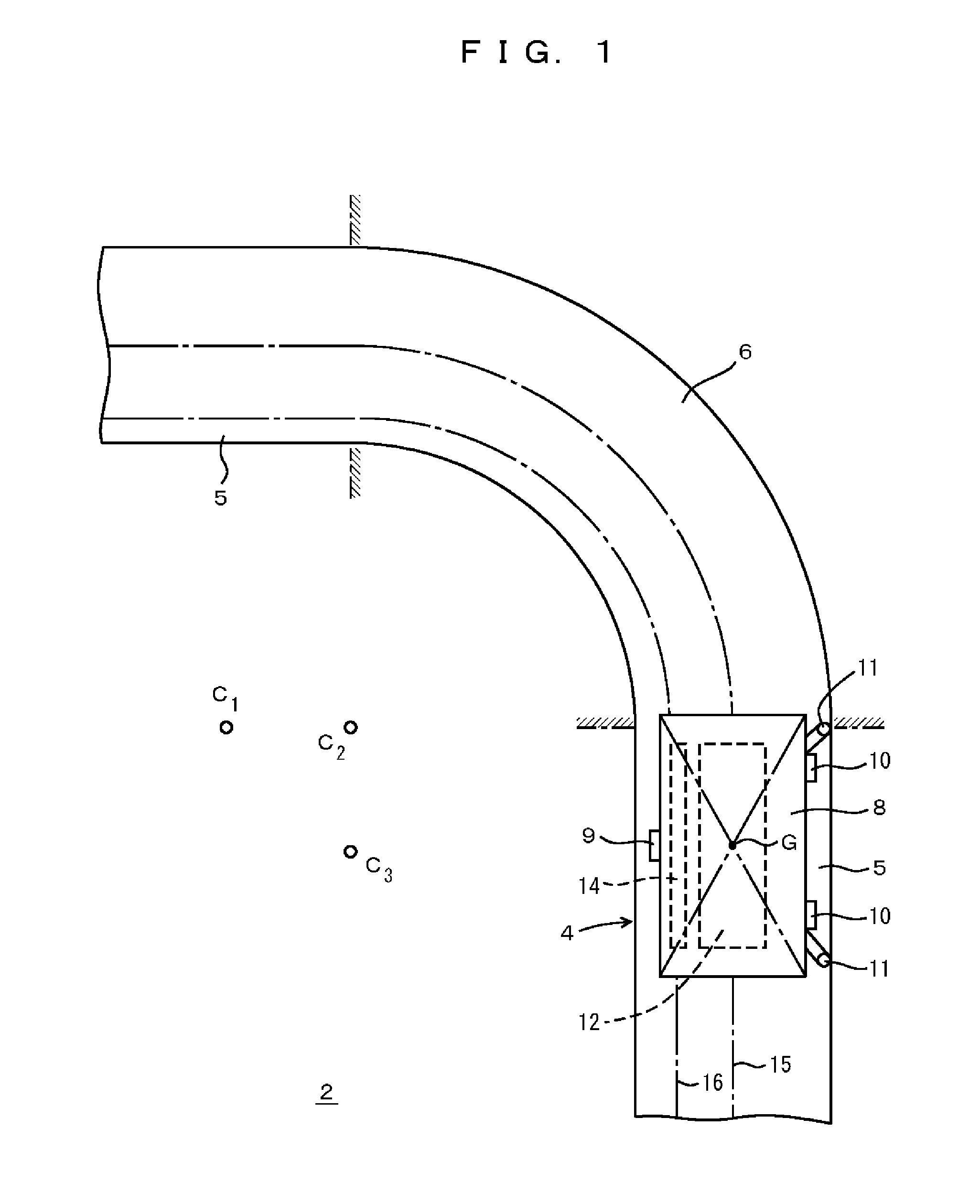
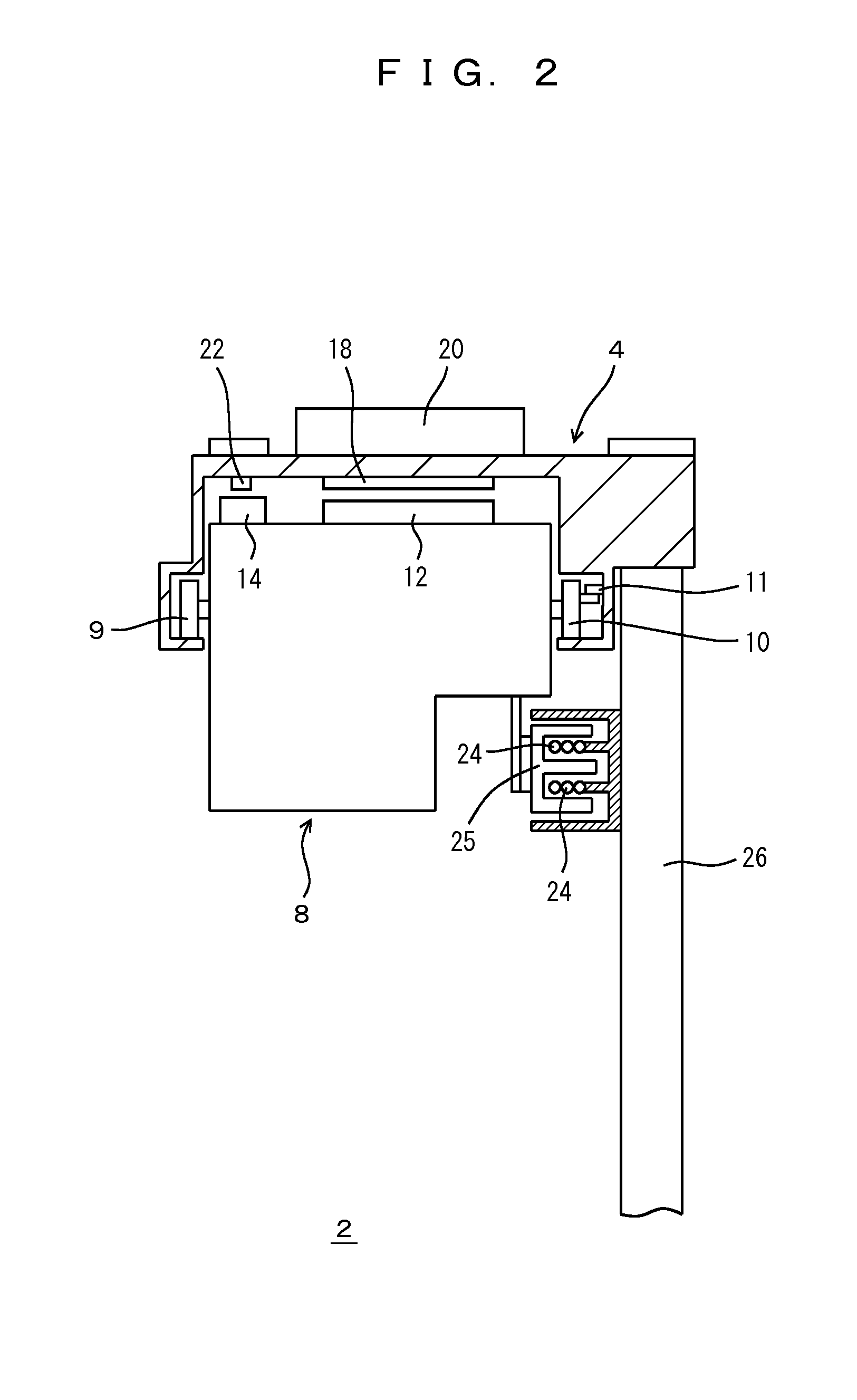
[0022]A moving body system 2 of preferred embodiments is shown in FIGS. 1 to 7. In these diagrams, reference numeral 4 denotes the trajectory along which a moving body 8 travels, and includes straight sections 5 and a curved section 6. The moving body 8 travels along the trajectory 4 preferably using three wheels including a wheel 9 and a pair of wheels 10, for example, and is guided by a pair of guide rollers 11 that are guided by the trajectory 4 in the curved section 6. Although the trajectory 4 changes direction by 90 degrees in the curved section 6, the curved section 6 preferably is not a quarter circle, and has a large radius of cu...


PUM


Abstract

A detector detects positions of a moving body in a travel direction at a position shifted from a center of control of travel of the moving body in a direction different than the travel direction of the moving body. Positions of the center of control in the travel direction relative to the output of the detector is stored in a storage unit for at least a curved section of a travel route of the moving body, and the travel of the moving body is controlled by a controller, based on the positions of the center of control read out from the storage unit.

Description

BACKGROUND OF THE INVENTION[0001]1. Field of the Invention[0002]The present invention relates to detecting a position of a moving body and controlling travel.[0003]2. Description of the Related Art[0004]Conventionally known moving body systems include, for example, loaders for transferring articles such as workpieces or tools to and from equipment such as a machine tool, and overhead traveling vehicle systems for transferring articles such workpieces or reticles to and from equipment such as a semiconductor fabrication device. While providing a curved section on the trajectory of a moving body increases the flexibility with which equipment is disposed, feedback control of the travel cannot be carried out if the position of the moving body cannot be accurately measured in the curved section. Also, while it is convenient if the moving body can transfer articles to and from equipment in the curved section, this requires that the position of the moving body in the curved section be accu...

Claims


Application Information

Patent Timeline
Patent Type & Authority Patents(United States)
IPC IPC(8): G05D1/10B61L25/02G05D1/02B65G54/02
CPCG05D1/0259B61L25/026B65G54/02
Inventor HANAKA, SATOSHISHIMIZU, TETSUYA
Owner MURATA MASCH LTD
Why Eureka
Try Eureka