Exposure apparatus and method of configuring exposure apparatus

a technology of light exposer and exposure apparatus, which is applied in the direction of microlithography exposure apparatus, printers, instruments, etc., can solve the problems of deterioration of the illumination beam provided by the light exposer, increased total cost, and increased manufacturing cost of the mask, so as to reduce the energy density of the beam, reduce the cost of manufacturing, and prevent or minimize damage to the exposure beam generator

Active Publication Date: 2016-03-29
SAMSUNG DISPLAY CO LTD
View PDF14 Cites 0 Cited by
  • Summary
  • Abstract
  • Description
  • Claims
  • Application Information

AI Technical Summary

Benefits of technology

[0011]An embodiment of the present invention is related to a light exposer and a light exposure device configuration method having advantages of preventing or minimizing damage to an exposure beam generator when the exposure beam generator is used for a long period of time.
[0032]As described above, the lens for changing (e.g., enlarging) the diameter of the beam is added to the exposure beam generator to reduce the energy density of the beam such that damage to the exposure beam generator may be prevented or minimized even if the exposure beam generator has been used for a long period of time. As a result, the illumination of the exposure beam and associated uniformity may be substantially constant, to ensure consistency in the exposure process of photolithography. Advantageously, productivity and quality of display device manufacturing may be optimized.

Problems solved by technology

Nevertheless, if the size of a mask corresponding to the mother substrate also is increased, the manufacturing cost of the mask may be substantially increased; as a result, the total cost may be increased.
Nevertheless, printing methods may be applicable to only a portion of the display device manufacturing process, and some steps in the manufacturing process may still require one or more masks.
Typically, the illumination of the exposure beam provided by the light exposer may be deteriorate due to the long-time usage of the light exposer.
For example, when the light exposer has been used more than 30 days, damage may be generated in an optic system of the exposure beam generator, and causing the illumination of the exposure beam to deteriorate.
As a result, the illumination uniformity of the exposure process may substantially deteriorate, and the exposure capacity of may substantially deteriorate.

Method used


Image

  • Exposure apparatus and method of configuring exposure apparatus
  • Exposure apparatus and method of configuring exposure apparatus
  • Exposure apparatus and method of configuring exposure apparatus

Examples


Embodiment Construction

[0041]The present invention will be described more fully hereinafter with reference to the accompanying drawings, in which embodiments of the invention are shown. As those skilled in the art would realize, the described embodiments may be modified in various different ways, all without departing from the spirit or scope of the present invention.

[0042]In the drawings, the thickness of layers, films, panels, regions, etc., may be exaggerated for clarity. Like reference numerals may designate like elements throughout the specification. It will be understood that when an element such as a layer, film, region, or substrate is referred to as being “on” another element, it can be directly on the other element or intervening elements may also be present. In contrast, when an element is referred to as being “directly on” another element, there are no intervening elements present.

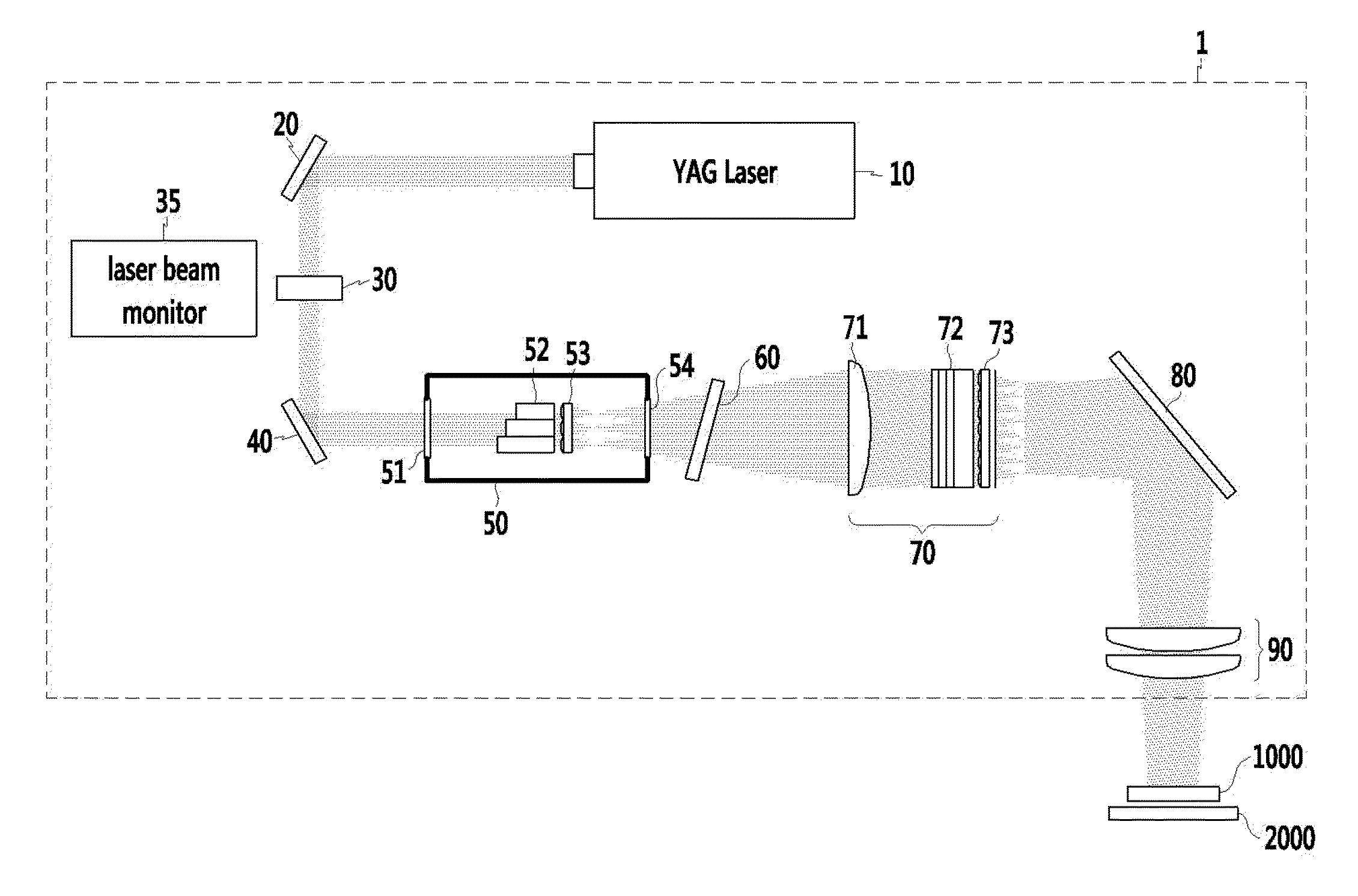
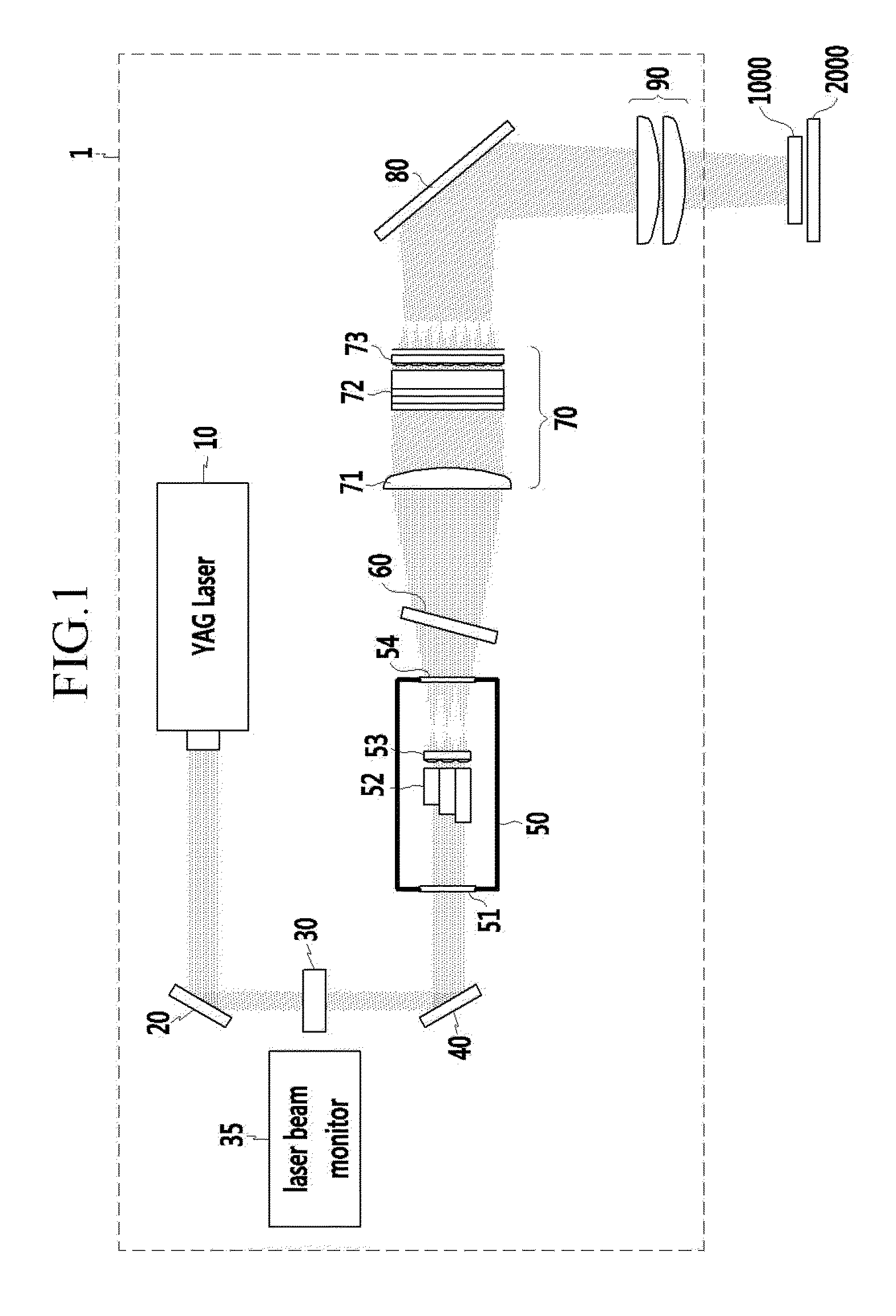
[0043]Now, a light exposer and an exposure path according to an embodiment of the present invention will be descri...


PUM

PropertyMeasurementUnit
diameteraaaaaaaaaa
diameteraaaaaaaaaa
diameteraaaaaaaaaa

Abstract

A light exposer according to an embodiment of the present invention includes an exposure beam generator generating an exposure beam, and a vacuum chamber passing the exposure beam generated by the exposure beam generator and including a first fly eye lens having a plurality of convex lens like fly eyes. The exposure beam generator includes an oscillator including an oscillator pumping chamber, a first prism and a second prism, and a first exposure beam diameter changing lens positioned before the first prism and enlarging a diameter of the exposure beam.

Description

CROSS-REFERENCE TO RELATED APPLICATION[0001]This application claims priority to and the benefit of Korean Patent Application No. 10-2012-0017331 filed in the Korean Intellectual Property Office on Feb. 21, 2012, the entire contents of which are incorporated herein by reference.BACKGROUND[0002](a) Field[0003]The present invention relates to a light exposer and a controlling method of a light exposer.[0004](b) Description of the Related Art[0005]In manufacturing display devices, the size of a mother substrate may be increased to accommodate more display device parts on the mother substrate, thereby reducing the unit cost for each display device. Nevertheless, if the size of a mask corresponding to the mother substrate also is increased, the manufacturing cost of the mask may be substantially increased; as a result, the total cost may be increased.[0006]For avoiding the increased manufacturing cost that may be caused by the increased size of the mask, the use of a mask may be minimized...

Claims


Application Information

Patent Timeline
Patent Type & Authority Patents(United States)
IPC IPC(8): G03B27/42G03F7/20
CPCG03F7/70141G03F7/70075G03F7/20G03F9/00
Inventor TORIGOE, TSUNEMITSUKIM, CHANG, HOONSEO, KAB, JONG
Owner SAMSUNG DISPLAY CO LTD
Why Eureka
Try Eureka