Thermally actuated power element with integral valve member

a technology of power element and integral valve member, which is applied in the direction of machines/engines, process and machine control, instruments, etc., can solve the problems of limiting the free space that the actuator may travel, reducing fluid flow, and inhibiting the effective flow of fluid through the system, etc., to avoid the reduction of fluid flow, improve hydrodynamic characteristics, and high pressure

Active Publication Date: 2016-03-29
ROSTRA VERNATHERM
View PDF20 Cites 5 Cited by
  • Summary
  • Abstract
  • Description
  • Claims
  • Application Information

AI Technical Summary

Benefits of technology

[0015]In one embodiment, the abutment that engages the piston first end is a webbed support structure. The webbed support structure has a detent which acts as a seat for the actuator. In this embodiment, a plurality of concentrically arranged tabs act as the abutment engaging the return member second end. The webbed support structure and the tabs cooperate to center the power element within the manifold, and prevent high pressure and fast flowing fluids from dislodging the actuator and / or disrupting the seal.
[0016]The thermally actuated power element and flow-control assembly of the present disclosure provide advantages over and relative to the prior art. For example, the configuration of the valve member, particularly the configuration of the flow depressions, gives the power element improved hydrodynamic characteristics over the prior art. This is particularly important in fluid flow systems that may be highly pressurized and / or have large volumes of fluid flowing through the system at relatively high velocity.
[0017]As a result of the improved hydrodynamics, the power element is more compact than prior art elements. Less valve throw, or distance between the open and closed positions, is required to achieve the same amount of fluid flow in comparison to prior art power elements. Consequently, the manifold may also be smaller while avoiding the reduction in fluid flow that could result if the actuator were to project into the flow path (i.e. the flow-inlet conduit).

Problems solved by technology

Under certain circumstances, the size and structure of the actuator may inhibit the effective flow of fluid through the system.
Decreased fluid flow is particularly troublesome in systems having sensitive components requiring an adequate supply of fluid, yet other structural considerations limit the free space that the actuator may travel between the open and closed positions.
Thus, spacial constraints limit the effectiveness of wax actuators in certain environments.

Method used


Image

  • Thermally actuated power element with integral valve member
  • Thermally actuated power element with integral valve member
  • Thermally actuated power element with integral valve member

Examples


Embodiment Construction

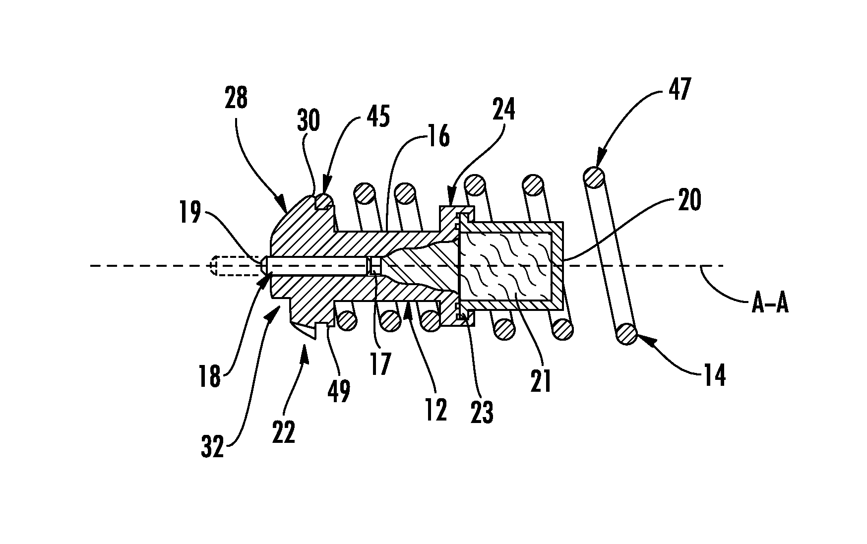
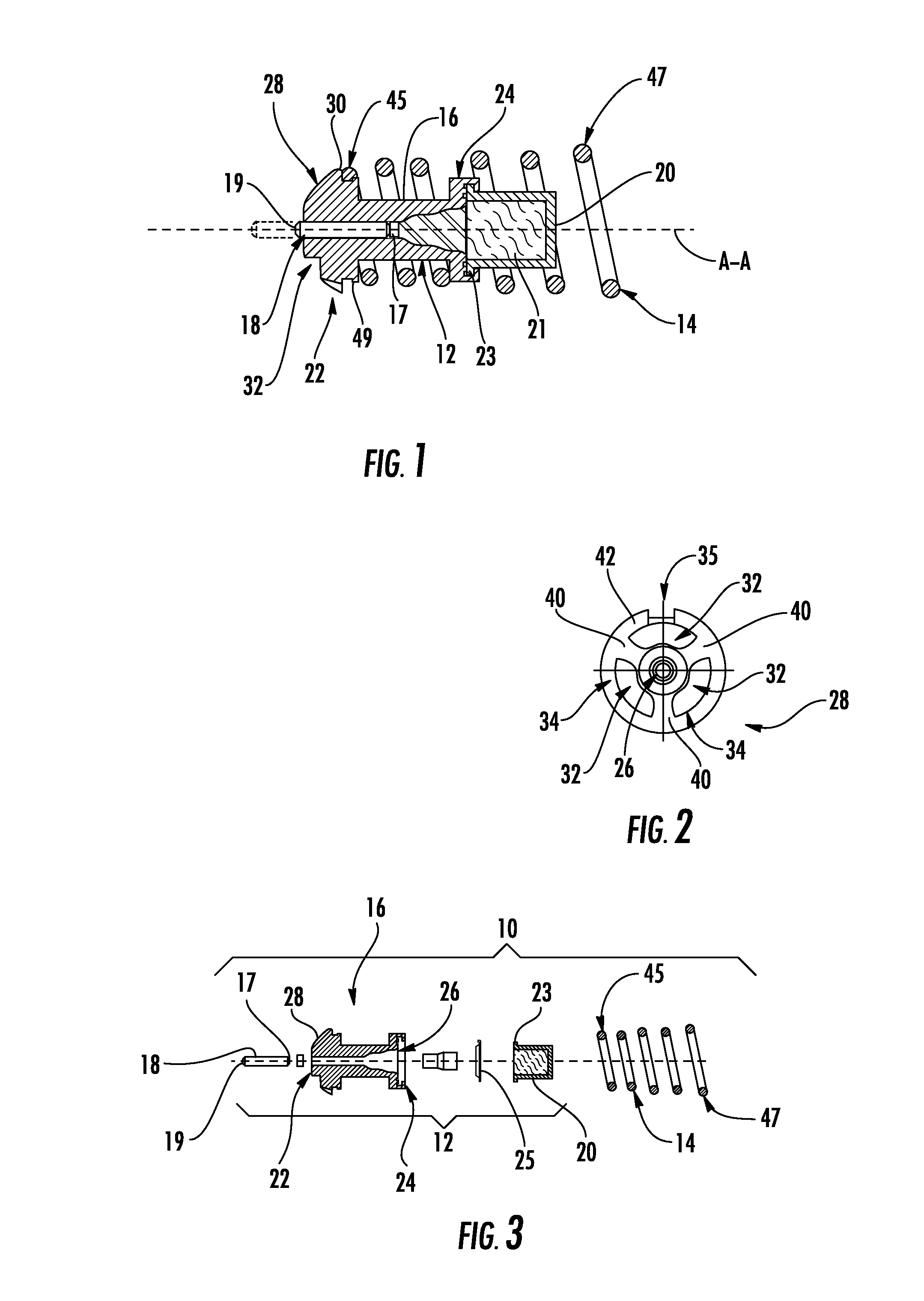
[0026]With reference to the drawings wherein like numerals represent like parts throughout the figures, a thermally actuated power element with integral valve member 10 is disclosed herein. Referring to FIG. 1, the power element 10 has a longitudinal axis A-A, an actuator 12, and a generally cylindrical return member 14. The actuator 12 comprises a guide 16 coaxial with the longitudinal axis A-A, a piston 18, and a generally concave cup 20. The cup 20 contains a thermally active wax pellet 21.

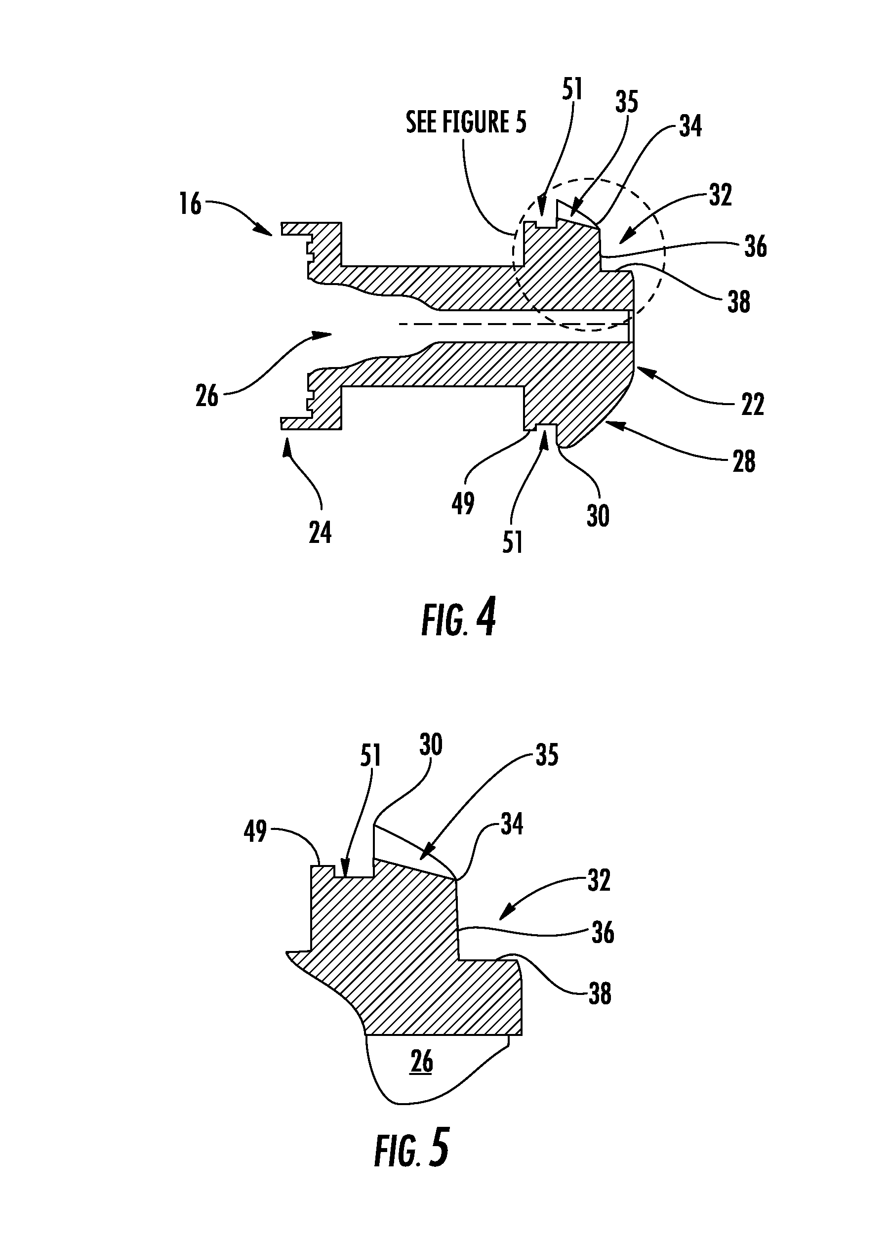
[0027]As shown in FIGS. 1, 2, and 4, the guide 16 has first and second axial guide ends 22 and 24, respectively. The guide 16 defines a generally cylindrical bore 26 between the first and second guide ends 22 and 24. As seen in FIGS. 1 and 3, the cup 20 has a peripheral lip 23 which projects radially outwardly, and the guide second end 24 is crimped around the peripheral lip 23 to attach the cup to the guide 16.

[0028]The piston 18 has axially opposed first and second piston ends 19 and 17, resp...


PUM


Abstract

A thermally actuated power element comprising an actuator having a guide, defining a generally cylindrical bore extending between first and second guide ends. The guide first end has a generally convex valve member projecting radially between the bore and a valve member periphery, defining a plurality of substantially identical flow depressions. The flow depressions are configured radially intermediate the cylindrical bore and the periphery, while an annular valve member seal surface extends between a radial boundary of the flow depressions and the periphery. A piston having axially opposed first and second piston ends is partially received in the generally cylindrical cavity. A generally concave cup defines a cavity and contains a thermally active pellet, and a diaphragm is received in the guide second end intermediate the cup and said piston. A generally cylindrical return member engages the guide adjacent the periphery.

Description

BACKGROUND OF THE DISCLOSURE[0001]The present disclosure relates to thermally actuated flow-control valves. More particularly, the present disclosure relates to valves including wax-filled actuators employed to control the flow of transmission fluid or coolant in automatic transmissions or other heat producing automotive systems.[0002]The use of wax-filled actuators or wax motors in automotive systems is well known. Wax actuators typically utilized in automotive systems are employed to regulate the flow of engine fluids and prevent overheating. Such actuators are designed to open or close in response to a predetermined change in temperature. Wax-filled actuators are reliable temperature sensitive actuators that require no external energy, such as electricity or externally applied actuation force, such as a cable or lever.[0003]In temperature sensitive automotive systems, there is no or restricted flow of fluid to designated fluid passages when the fluid is cool and the wax actuator ...

Claims


Application Information

Patent Timeline
Patent Type & Authority Patents(United States)
IPC IPC(8): G05D23/13G05D23/02F01P7/02G05D23/185
CPCG05D23/022
Inventor LAMB, KEVIN, W.LIONELLO, KENNETH
Owner ROSTRA VERNATHERM
Why Eureka
Try Eureka