Magnetic driven rotation gas distribution device in gas-fluid multi-phase system
A gas distribution device, multiphase system technology, applied in chemical methods, dissolution, chemical/physical/physical-chemical stationary reactors that make liquids react with gaseous media, etc. Single, narrow adaptable surface and other problems, to achieve the effect of wide distribution, simplified installation, easy manufacturing and maintenance
- Summary
- Abstract
- Description
- Claims
- Application Information
AI Technical Summary
Problems solved by technology
Method used
Image
Examples
Embodiment 1
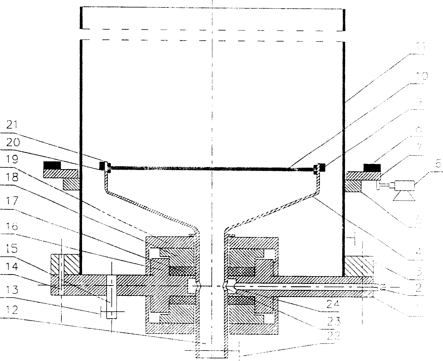
[0043] Attached figure 1 , make the distribution plate support 4 and the rotating hollow shaft 12 with stainless steel, and weld the distribution plate support frame 20 on the distribution plate support 4, and seal and fix an average aperture on the support frame 20 by the pressure plate 21 on the distribution plate. The 80mm porous sintered titanium plate 10 is used as the gas distribution plate, and two permanent magnets 9 are symmetrically installed on the side wall of the distribution plate support 4, and two gas introduction holes 23 are opened on the rotating hollow shaft 12 to make the distributor support plate 1 On the support plate 1, the gas inlet pipe hole 2, the sealing support ring 16 with outer thread and the sewage pipe hole are opened. The pressure ring 19 is sealed and connected with the distributor tray 1, and the tower 11 with an inner diameter of 10 cm and a height of 1 m is used as the main body of the tower, and the main body of the tower is sealed and co...
Embodiment 2
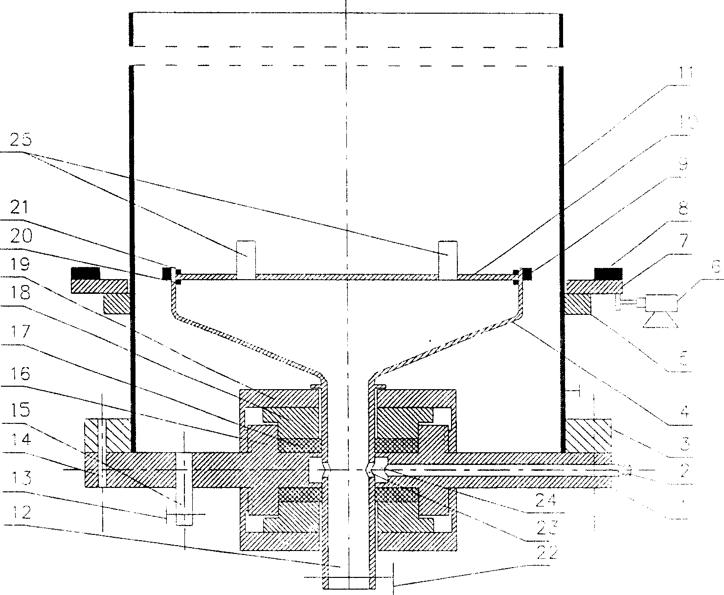
[0045]Attached figure 2 , make the distribution plate support 4 and the rotating hollow shaft 12 with stainless steel, and weld the distribution plate support frame 20 on the distribution plate support 4, and seal and fix a support plate 10 supporting the porous cylinder on the support frame 20 by the distribution plate pressing plate 21 Four porous cylinders 25 with an average aperture of about 20 microns and a height of 40 mm are symmetrically installed on the support plate 10 as gas distribution heads, and two permanent magnets 9 are symmetrically installed on the side wall of the distribution plate support 4. Two gas inlet holes 23 are opened on the hollow shaft 12 to make the distributor support plate 1, and the gas introduction pipe hole 2, the sealing support ring 16 with outer screw thread and the sewage pipe hole are opened on the support plate 1, and the distribution plate support 4 and The rotating shaft 12 is sealed and connected with the distributor tray 1 throug...
Embodiment 3
[0047] Example 3. Traditional stationary perforated plate gas distribution method for gas-liquid two-phase flow in quiet bubbling zone
[0048] With the magnetic transmission rotary gas distribution device of the gas-liquid multiphase system made in embodiment 1, add tap water in the tower (11), the height is 950mm, and the nitrogen in the compressed steel cylinder passes through the air inlet pipe (2), cloth The air chamber (24) and the gas inlet hole (23) on the hollow shaft pass through the gas distribution plate (10) and enter the tower, the gas volume flow rate is 220ml / min, the water phase and the gas phase are operated in countercurrent, and the volume flow rate is 570ml / min , do not start the motor (6) to ensure that the gas distribution plate (10) is still, and when the two-phase flow reaches a steady state, use saturated potassium nitrate solution as a tracer, and use the online automatic conductivity method liquid phase back-mixing measurement equipment to measure wa...
PUM
 Abstract
Description
Claims
Application Information
 - R&D
- Intellectual Property
- Life Sciences
- Materials
- Tech Scout
- Unparalleled Data Quality
- Higher Quality Content
- 60% Fewer Hallucinations
Browse by: Latest US Patents, China's latest patents, Technical Efficacy Thesaurus, Application Domain, Technology Topic, Popular Technical Reports.
© 2025 PatSnap. All rights reserved.Legal|Privacy policy|Modern Slavery Act Transparency Statement|Sitemap|About US| Contact US: help@patsnap.com


