Vibrator element, manufacturing method of vibrator element, sensor unit, and electronic apparatus

a manufacturing method and technology of vibrator elements, applied in the direction of generators/motors, turn-sensitive devices, instruments, etc., can solve the problems of inability to adjust, difficult to form the size of the tuning fork as designed, and difficulty in accurately adjusting a charge amount, etc., to achieve efficient suppression of leakage vibration, accurate adjustment, and high sensitivity

Active Publication Date: 2016-03-29
SEIKO EPSON CORP
View PDF16 Cites 3 Cited by
  • Summary
  • Abstract
  • Description
  • Claims
  • Application Information

AI Technical Summary

Benefits of technology

[0012]According to this application example, an output signal of the first adjustment vibrating arm and the second adjustment vibrating arm is made to be out of phase with an output signal generated in the detection vibrating arm due to leakage vibration of the excitation vibrating arm, and thereby it is possible to cancel out and suppress a leakage output of the excitation vibrating arm.
[0013]In addition, the amplitude of the output signal of the first adjustment vibrating arm is made to be larger than the amplitude of the output signal of the second adjustment vibrating arm, and thereby it is possible to perform a so-called coarse adjustment in the first adjustment vibrating arm and to perform a so-called fine adjustment in the second adjustment vibrating arm. As a result, it is possible to suppress a leakage signal of the excitation vibrating arm widely and with high accuracy.Application Example 2
[0019]In the vibrator element with this configuration, since the vibrating arm of an excitation system and the vibrating arm of a detection system, and the vibrating arm of an adjustment system are separated from each other, electrostatic coupling is reduced between electrodes or wires of the vibrating arm of the excitation system and the vibrating arm of the detection system, and the vibrating arm of the adjustment system, and thus it is possible to suppress deterioration of detection sensitivity due to provision of the vibrating arm of the adjustment system.Application Example 5
[0023]According to this application example, it is possible to provide a sensor unit having the vibrator element capable of achieving the effect according to any one of the above-described application examples.
[0029]This method is advantageous to miniaturization and enables an accurate adjustment to be performed as compared with a method in the related art of suppressing and adjusting a leakage output by processing a part of the exterior of the vibrator element, and thus it is possible to manufacture a vibrator element which is miniaturized and has high sensitivity.
[0030]In addition, an adjustable range is made to be wide in the coarse adjustment, and the accurate adjustment is made to be able to be performed in the fine adjustment. Therefore, it is possible to efficiently suppress leakage vibration.

Problems solved by technology

At this time, it is difficult to form the size of the tuning fork as designed due to etching anisotropy of the substrate, a variation in processing process, or the like.
However, in the method in which an amount of charge is adjusted by partially removing a pair of electrodes of the detection portion, in a case where an adjustment amount is large, a variation of a charge amount relative to a removal amount is required to be increased, and thus an accurate adjustment of a charge amount becomes difficult.
In addition, if a variation of a charge amount relative to a removal amount is made to be small, an adjustment range is narrowed, and thus there is a problem in that the adjustment cannot be performed.

Method used


Image

  • Vibrator element, manufacturing method of vibrator element, sensor unit, and electronic apparatus
  • Vibrator element, manufacturing method of vibrator element, sensor unit, and electronic apparatus
  • Vibrator element, manufacturing method of vibrator element, sensor unit, and electronic apparatus

Examples


Embodiment Construction

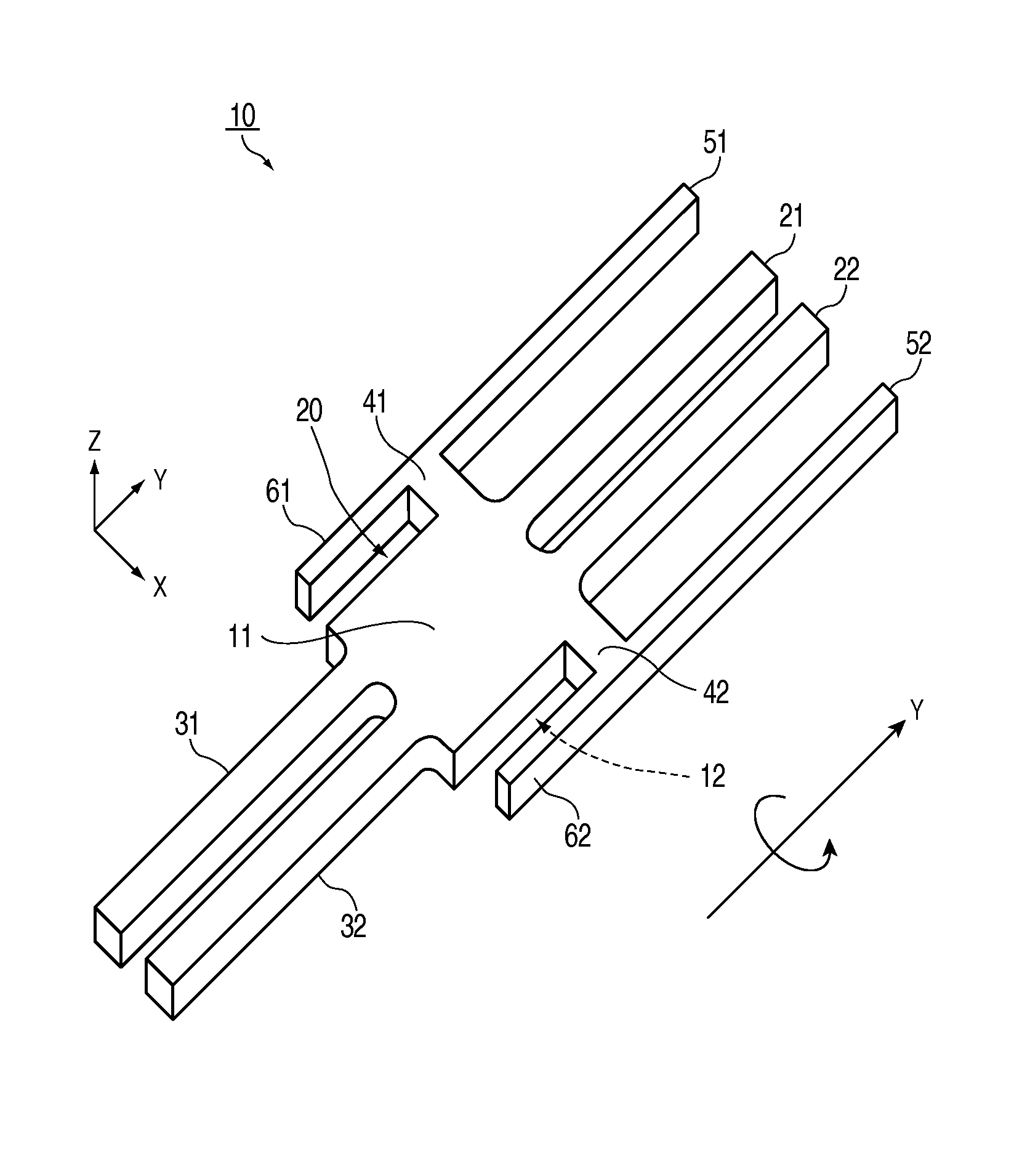
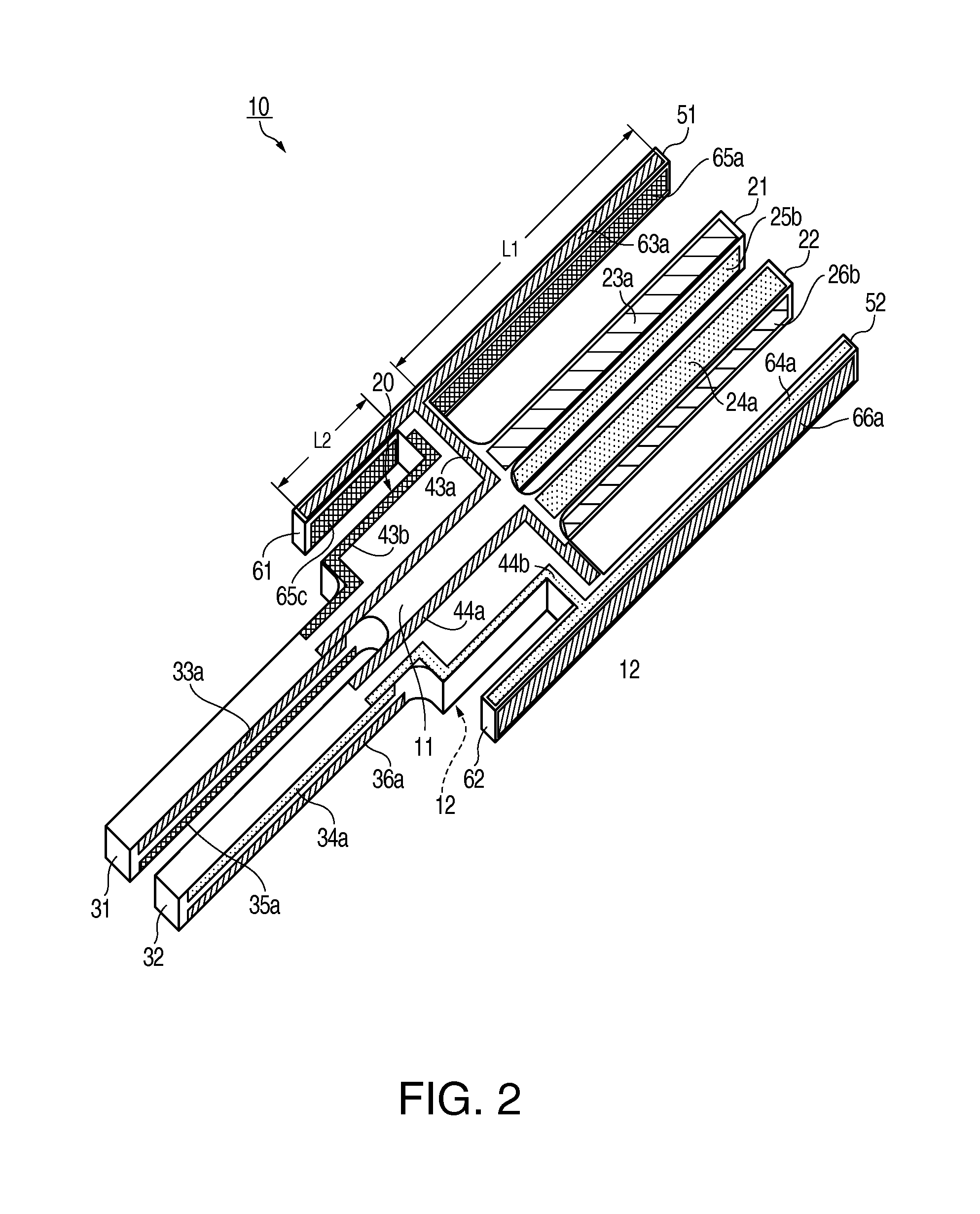
[0043]Hereinafter, embodiments of the invention will be described with reference to the drawings.

[0044]In addition, the drawings referred to in the following description are schematic diagrams in which vertical and horizontal scales of each member or each portion are different from practical ones, in order to show each member in a recognizable size.

Vibrator Element

[0045]First, a configuration of the vibrator element will be described with reference to the drawings. In the present embodiment, a vibration gyro-element will be described as a specific example of the vibrator element.

[0046]FIG. 1 is a perspective view illustrating a schematic configuration of a vibration gyro-element as the vibrator element. As shown in FIG. 1, the vibration gyro-element 10 includes a base portion 20 which is formed by processing a base material (a material forming a main portion) using wet etching dry etching, or the like, excitation vibrating arms 21 and 22, detection vibrating arms 31 and 32, and firs...


PUM

PropertyMeasurementUnit
vibration frequencyaaaaaaaaaa
physical quantityaaaaaaaaaa
lengthaaaaaaaaaa

Abstract

A vibration gyro-element includes a base portion, an excitation vibrating arm and a detection vibrating arm extending from the base portion, and a first adjustment vibrating arm and a second adjustment vibrating arm extending from the base portion and vibrating along with excitation vibration of the excitation vibrating arm, wherein an output signal of the first adjustment vibrating arm at least is out of phase with respect to an output signal of leakage vibration of the detection vibrating arm, and wherein an amplitude of the output signal of the first adjustment vibrating arm is larger than an amplitude of the output signal of the second adjustment vibrating arm.

Description

BACKGROUND[0001]1. Technical Field[0002]The present invention relates to a vibrator element, a manufacturing method of the vibrator element, and a sensor unit and an electronic apparatus using the vibrator element.[0003]2. Related Art[0004]There is an angular velocity sensor (a vibration gyro sensor) or the like which is used for, for example, vehicle body control of a vehicle, own-vehicle position detection of a car navigation system, vibration control correction (so-called camera shake correction) of a digital camera or a video camera, and the like, and detects a physical quantity such as angular velocity, acceleration, or the like, as a sensor element (for example, JP-A-2008-14887).[0005]An angular velocity sensor disclosed in JP-A-2008-14887 has a tuning fork which includes two arms and a base portion which connects first ends of the two arms to each other. In addition, in the angular velocity sensor disclosed in JP-A-2008-14887, the tuning fork is made of a non-piezoelectric bo...

Claims


Application Information

Patent Timeline
Patent Type & Authority Patents(United States)
IPC IPC(8): G01C19/56H01L41/47H01L41/107H01L41/25G01C19/5607H01L41/047H01L41/22H01L41/253H01L41/29
CPCH01L41/107G01C19/5607H01L41/047H01L41/25Y10T29/42H10N30/40H10N30/03H10N30/87
Inventor MATSUO, ATSUSHI
Owner SEIKO EPSON CORP
Why Eureka
Try Eureka