Leakage current detection device for appliances

a leakage current detection and appliance technology, applied in the direction of measurement devices, short-circuit testing, instruments, etc., can solve the problems of important safety of leakage current signals, and achieve the effect of accurate detection of actual leakage current signals and improved safety

Active Publication Date: 2018-01-11
LI CHENGLI
View PDF2 Cites 1 Cited by
  • Summary
  • Abstract
  • Description
  • Claims
  • Application Information

AI Technical Summary

Benefits of technology

[0003]In a leakage current detection devices that have both leakage current detection function and self test function, the self test signals sometimes interfere with actual leakage current signals. For example, the self test signals may be superimposed on the actual leakage current signals, or cancel out the actual leakage current signals. Embodiments of the present invention provide a leakage current detection device and electrical connection device incorporating the leakage current detection device that can avoid such undesirable effects, and can ensure that the leakage current detection function and the self test functions do not interfere with each other.
[0005]Using the above structure, the detection of the actual leakage current occurs after the simulated leakage current is deactivated, and based on such detection, the power source is disconnected. Therefore, the simulated leakage current will not interfere with the actual leakage current, which improves the reliability of the device and improves safety.
[0013]In one embodiment, the delay sub-unit is an RC circuit. This can achieve the delay using a simple structure.
[0017]In summary, embodiments of the present invention can separate the self test function and the leakage current detection function in the time domain, in order to prevent the simulated leakage signal from interfering with the actual leakage signal. As a result, the leakage current detection device can more accurately detect actual leakage current signals, which improves safety.

Problems solved by technology

Electrical appliances are widely used, and their safety is an important issue.

Method used


Image

  • Leakage current detection device for appliances
  • Leakage current detection device for appliances
  • Leakage current detection device for appliances

Examples


first embodiment

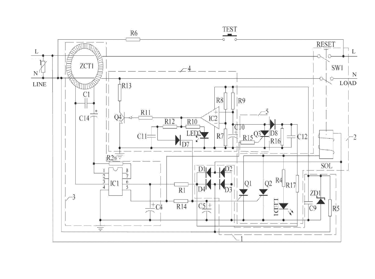
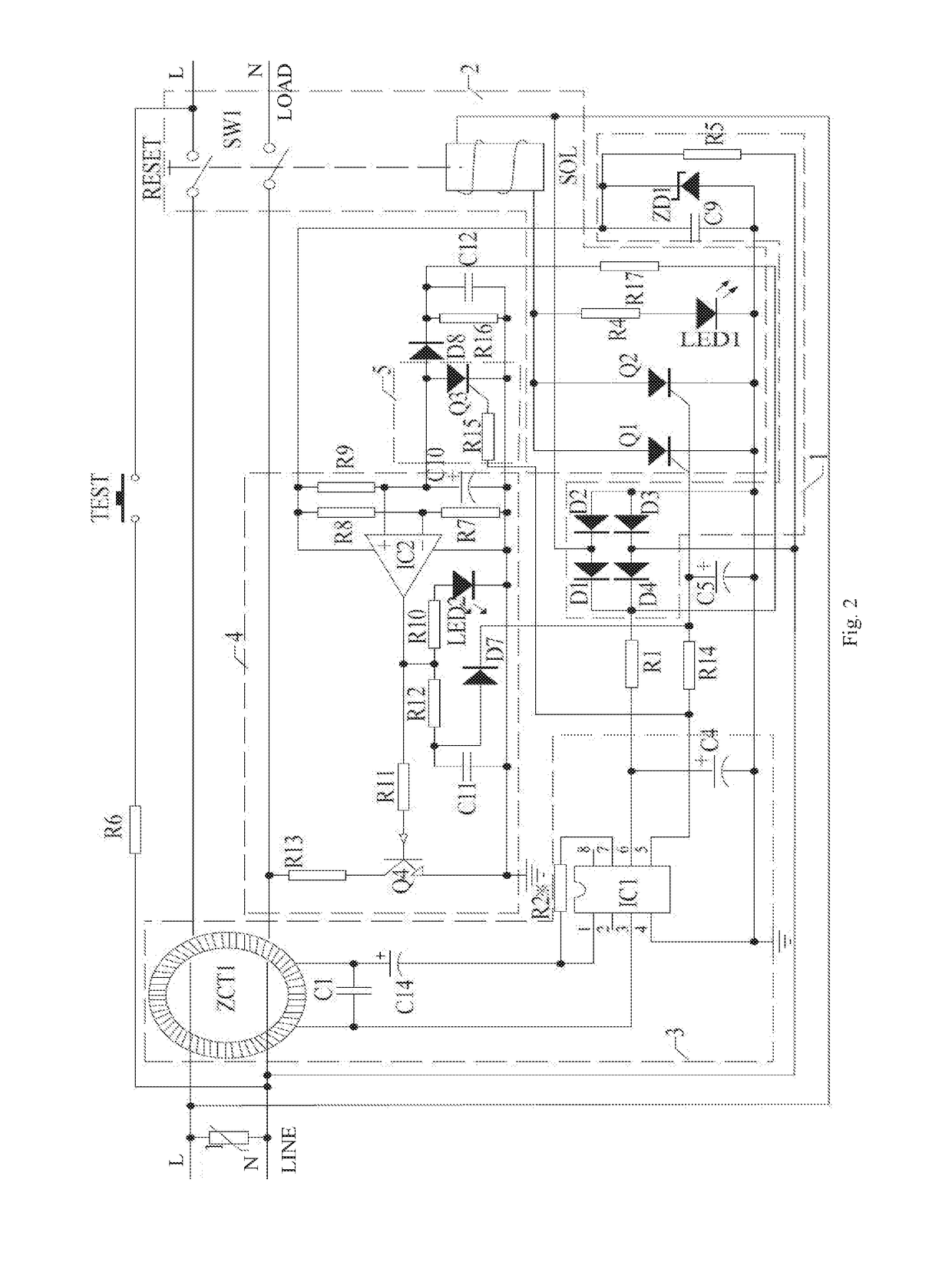
[0031]FIG. 2 is a circuit diagram of a leakage current detection device according to the present invention.

[0032]As shown in FIG. 2, the power line disconnect unit 2 includes: a trip solenoid SOL, power switch SW1, silicon-controlled rectifiers (SCR) Q1 and Q2, resistor R4, and light emitting diode LED1 connected as shown. It should be understood that the SCR Q1 may be replaced by other devices that have a switching function, such as MOS transistors. Here, two redundant SCRs Q1 and Q2 are used to ensure that the trip solenoid SOL is activated and the power switch SW1 disconnects the power lines. Other numbers of SCRs may be used.

[0033]The leakage current detection unit 3 includes: a detector coil ZCT1 and processor chip IC1 connected as shown.

[0034]The self-test unit 4 includes: reference voltage generating sub-unit, a periodic voltage generating sub-unit, a comparator IC2, and a first transistor Q4 connected as shown. The reference voltage generating sub-unit generates a reference ...

second embodiment

[0045]FIG. 3 is a circuit diagram of a leakage current detection device according to the present invention. Main differences between the embodiment of FIG. 3 and the embodiment of FIG. 2 are that a relay is used to replace the trip solenoid SOL, and that two detector coils RING1 and RING2 are used. Using two detector coils improves the accuracy of leakage current detection.

[0046]FIG. 4 is a circuit diagram of a leakage current detection device according to a second embodiment of the present invention. A main difference between the embodiment of FIG. 4 and the embodiment of FIG. 3 is that a manual reset circuit is added. Thus, when the power is disconnected due to self test fault or leakage current, the manual reset may be used to close the reset switch RESET to resume normal operation of the device.


PUM


Abstract

A leakage current detection device includes a self-test unit for activating a simulated leakage current signal; a leakage current detection unit for detecting the simulated leakage current signal and the actual leakage current signal, where when at least one of them is present, the leakage current detection unit activates a trigger signal, and when both of them are absent, the leakage current detection unit deactivates the trigger signal; a self-test feedback turnoff unit for detecting the trigger signal, where when the trigger signal is detected, the self-test feedback turnoff unit deactivates the simulated leakage current signal before a predetermined time point; and a power line disconnect unit for detecting the trigger signal after the predetermined time point, and when the trigger signal is detected, it disconnects the power between the power source and the load.

Description

BACKGROUND OF THE INVENTIONField of the Invention[0001]This invention relates to the field of electrical appliance and related circuitry, and in particular, it relates to a leakage current detection device and electrical connection device incorporating the leakage current detection device.Description of the Related Art[0002]Electrical appliances are widely used, and their safety is an important issue. Leakage current detection devices are provided for safety purposes. Leakage current detection devices that employ a relay and have both leakage current detection function and self test function are available.SUMMARY OF THE INVENTION[0003]In a leakage current detection devices that have both leakage current detection function and self test function, the self test signals sometimes interfere with actual leakage current signals. For example, the self test signals may be superimposed on the actual leakage current signals, or cancel out the actual leakage current signals. Embodiments of the...

Claims


Application Information

Patent Timeline
Patent Type & Authority Applications(United States)
IPC IPC(8): G01R35/00G01R31/02
CPCG01R35/007G01R31/025G01R31/52
Inventor LI, CHENGLI
Owner LI CHENGLI
Why Eureka
Try Eureka