Receiver and method for retrieving an information signal from a magnetic induction signal

a magnetic induction signal and information signal technology, applied in the direction of transmission, antennas, energy consumption reduction, etc., can solve the problems of deterioration of the received signal, reducing the obtainable communication speed, and deviation from desired specifications

Active Publication Date: 2016-03-29
OTICON
View PDF25 Cites 12 Cited by
  • Summary
  • Abstract
  • Description
  • Claims
  • Application Information

AI Technical Summary

Benefits of technology

[0013]The inventors of the present invention have discovered that, quite unexpectedly, direct sampling may be utilised in communication by means of modulated near-field magnetic induction (NFMI) signals without the above mentioned disadvantages, provided that the antenna circuit receiving the modulated NFMI signal is arranged within the reactive near-field thereof. Furthermore, it is advantageous that the antenna circuit is designed as a band-pass filter that is narrow enough to be used to suppress signals outside the communication channel, i.e. the antenna circuit is adapted to function as a channel-selection filter. As explained in the following, this allows for the omission of further substantive filtering of the received signal prior to digitising and for digitising the signal with low resolution, which radically reduces the power consumption of the receiving circuits. The achievable reduction in power consumption is surprisingly of several orders of magnitude and thus allows implementation of such receiving circuits in battery-driven devices such as hearing devices without substantially affecting the battery life.
[0015]Within the reactive near-field, the reactive coupling thus causes signal levels to be considerably higher than those predicted by the above mentioned law for the far-field. Communicating within the reactive near-field thus inherently causes a relatively strong discrimination of the communication signals over magnetic signals radiated by disturbing sources in the far-field. This effect in conjunction with the use of the antenna circuit as a narrow band-pass filter allows the communication signals to be predominantly represented in the electric signal provided by the antenna circuit. Disturbing signals from distant sources are inherently suppressed, so that a digitiser with a relatively small dynamic range may be used to digitise the communication signals. Thus, direct sampling of the received signal may be achieved without unacceptably high power consumption and without compromising the quality of the communication signals.

Problems solved by technology

However, the circuits used for mixing the modulated RF signal and for filtering the signal at the lower frequency are mainly analog and thus often deviate from desired specifications due to relatively large component tolerances and temperature drift of the component values.
This may lead to a deterioration of the received signal and may thus decrease the obtainable communication speed where the received signal comprises digital information.
Furthermore, the analog mixing and filtering circuits are often relatively complex and typically consume a substantial amount of power.
It is further not trivial to design analog circuits in which the mixing frequency and / or the filter bandwidth may be changed electronically, which adds to complexity and / or restricts the use of prior art receivers.
Direct sampling of modulated RF signals has, however, been almost impossible to realise in practice.
With the technology available today, these two requirements typically combine to cause unacceptably large power consumption in the digital conversion and filtering circuits.
In a typical setup, reducing the power consumption to an acceptable level would therefore require compromising the signal quality to an unacceptable degree.

Method used


Image

  • Receiver and method for retrieving an information signal from a magnetic induction signal
  • Receiver and method for retrieving an information signal from a magnetic induction signal
  • Receiver and method for retrieving an information signal from a magnetic induction signal

Examples


Embodiment Construction

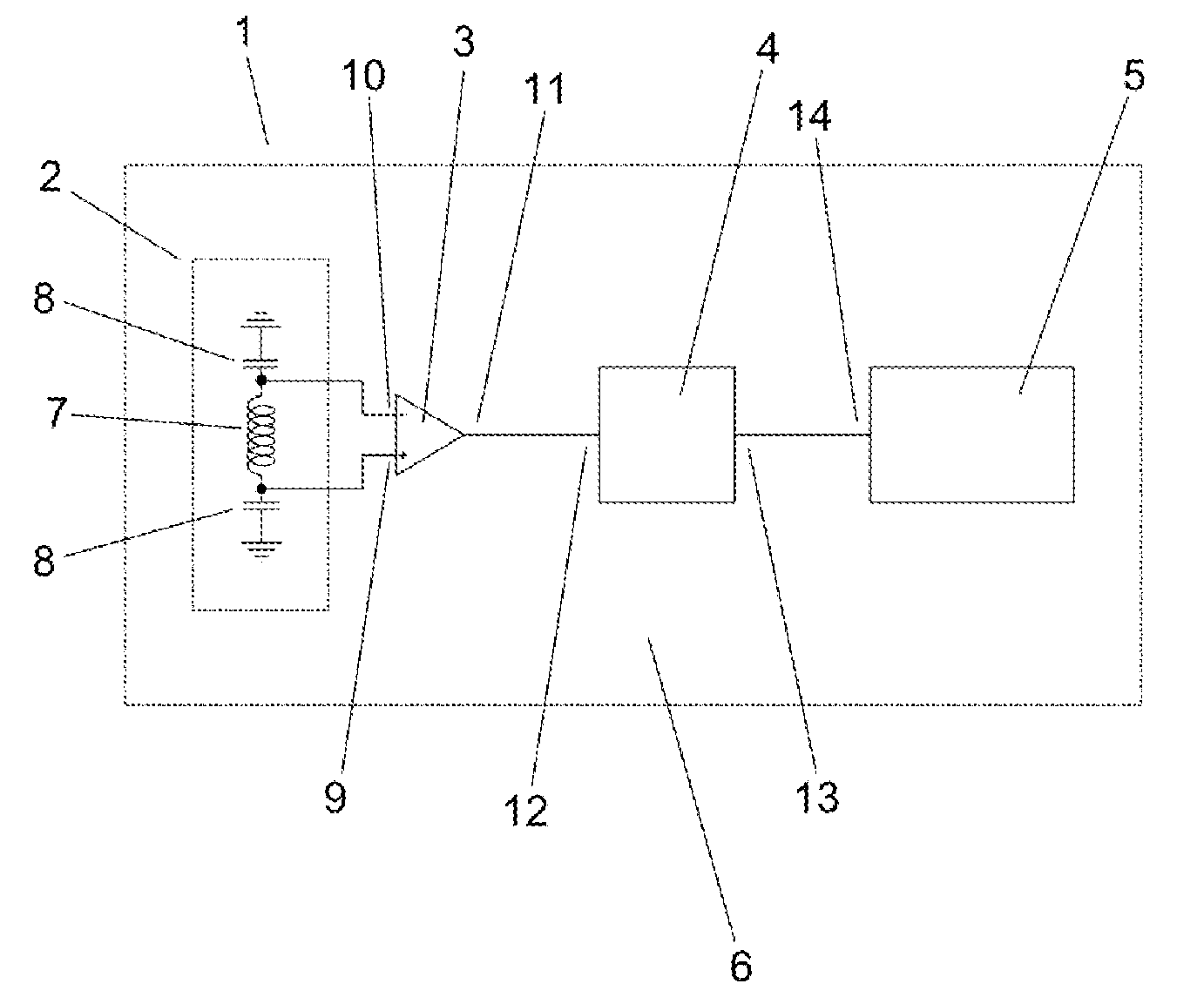
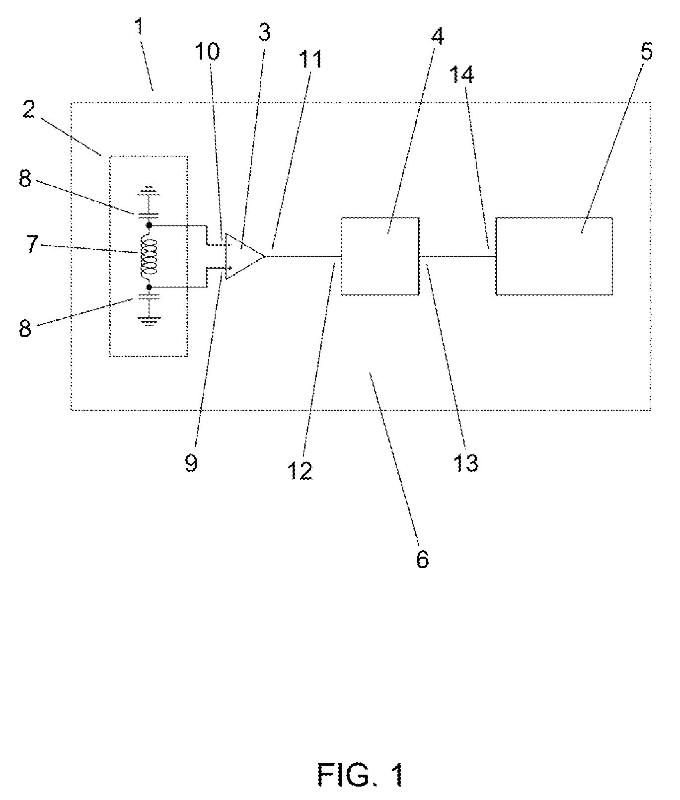
[0025]The receiver 1 shown in FIG. 1 comprises an antenna circuit 2, a low-noise amplifier 3, a comparator 4 and a digital demodulator 5 connected to form a signal path 6. The antenna circuit 2 comprises an antenna coil 7 with two terminals and two tank capacitors 8. One terminal of each tank capacitor 8 is connected to a respective terminal of the antenna coil 7, and the respective other terminals of the tank capacitors 8 are connected to a ground-plane of the receiver 1. The terminals of the antenna coil 7 are further connected respectively to a positive input terminal 9 and a negative input terminal 10 of the low-noise amplifier 3. An output terminal 11 of the low-noise amplifier 3 is connected to an input terminal 12 of the comparator 4. An output terminal 13 of the comparator 4 is connected to an input terminal 14 of the digital demodulator 5.

[0026]The antenna coil 7 and the tank capacitors 8 form a passive, narrow band-pass filter with a centre frequency of 4 MHz and a 3-dB ba...


PUM


Abstract

A receiving antenna circuit is arranged in a reactive near-field of a modulated magnetic induction signal and forms a narrow band-pass filter. The output of the antenna circuit is not subjected to any frequency translation prior to digitizing, and the signal may nevertheless be digitized with low resolution, which radically reduces the power consumption of the receiving circuits. The reduction in power consumption is of several orders of magnitude, which allows implementation of such receiving circuits in battery-driven devices such as hearing devices without substantially affecting the battery life.

Description

CROSS REFERENCE TO RELATED APPLICATIONS[0001]This nonprovisional application claims the benefit of U.S. Provisional Application No. 61 / 483,075 filed on May 6, 2011 and to patent application Ser. No. 11 / 165,050.3 filed in Europe, on May 6, 2011. The entire contents of all of the above applications is hereby incorporated by reference.TECHNICAL FIELD[0002]The present invention relates to a receiver and a method for retrieving an information signal from a magnetic induction signal, and to a use of such a receiver.[0003]The invention may e.g. be useful in wireless communication between body-worn devices, such as hearing devices and auxiliary devices. Hearing devices may include hearing aids for compensating for a hearing-impaired person's loss of hearing capability or listening devices for augmenting a normal-hearing person's hearing capability.BACKGROUND ART[0004]WO2002 / 030154A1 discloses a hearing aid comprising a radio-frequency (RF) receiver in which an analog frequency-modulated RF ...

Claims


Application Information

Patent Timeline
Patent Type & Authority Patents(United States)
IPC IPC(8): H04R25/00H01Q7/00H04B5/00H01Q1/27
CPCH04B5/0075H01Q1/273H01Q7/005H04B5/0006H04R25/554H04R25/558H04R2225/51H04R2460/03Y02D30/70
Inventor CHRISTENSEN, KARE, TAISJENSEN, RASMUS, GLARBORG
Owner OTICON
Why Eureka
Try Eureka