
Stabilizer link

a stabilizer and link technology, applied in the direction of pivotal connections, mechanical devices, transportation and packaging, etc., can solve the problems of low sealing performance, noise, and irregular rotating frictional resistance, and achieve the effect of reducing the tension in the dust cover and improving sealing performan

Active Publication Date: 2016-04-05
HYUNDAI MOTOR CO LTD
View PDF7 Cites 1 Cited by
  • Summary
  • Abstract
  • Description
  • Claims
  • Application Information

AI Technical Summary

Benefits of technology

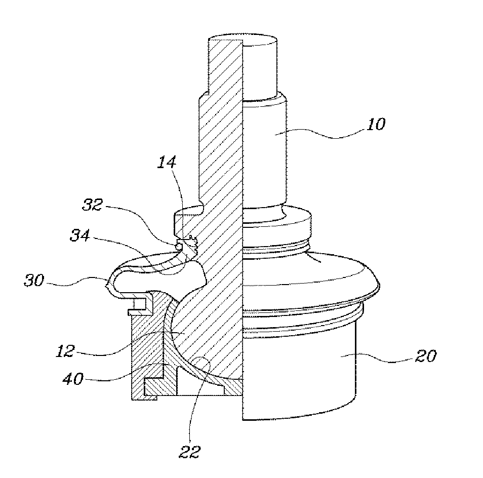
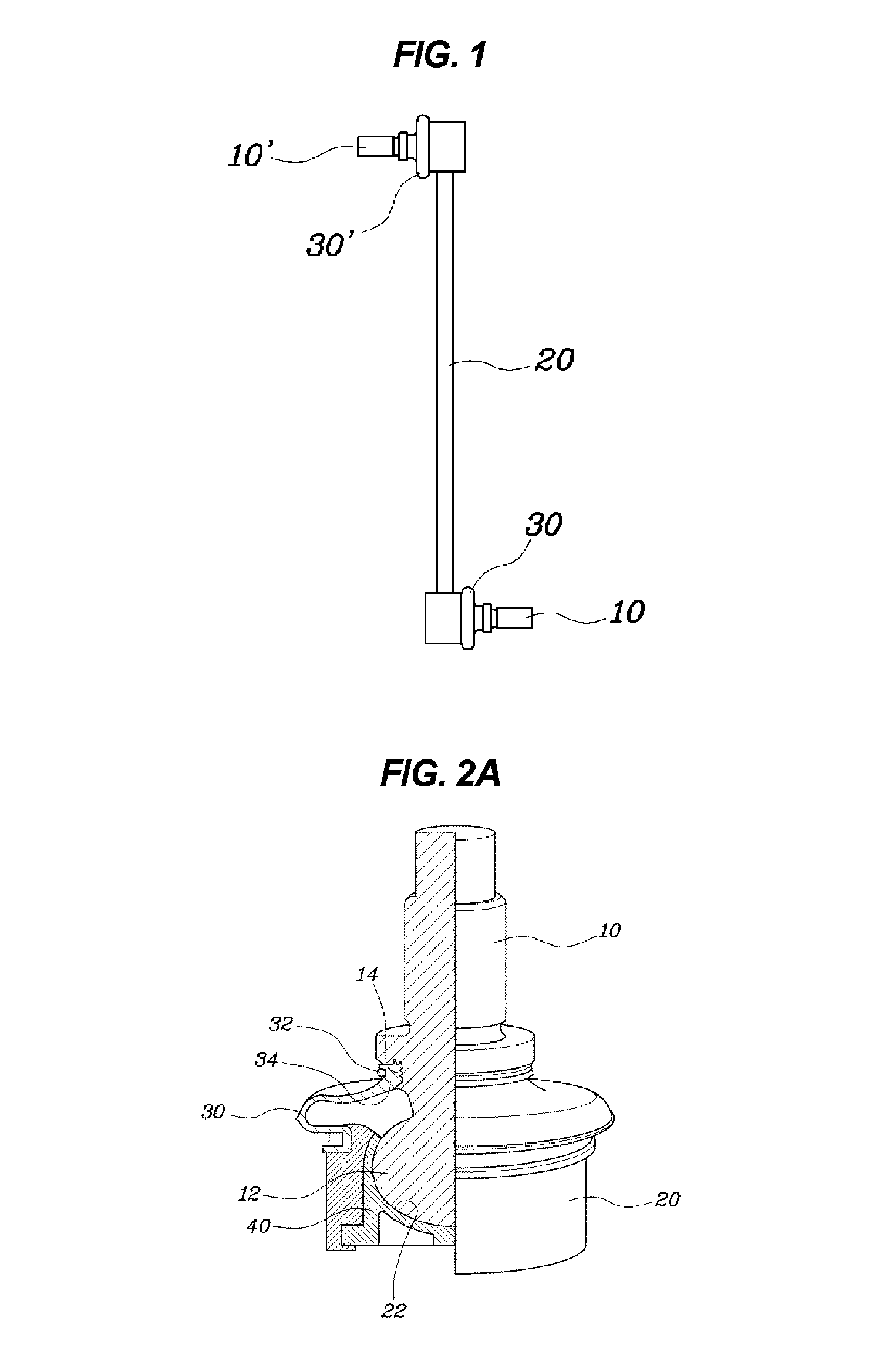
The design effectively minimizes impurity invasion and noise by maintaining reduced tension in the dust cover and enhancing sealing performance at the lower end of the stabilizer link.

Problems solved by technology

However, the ball joints which are disposed on the upper end and the lower end of the stabilizer link are subjected to irregular rotating frictional resistances in the ball studs due to part and assembly tolerances.
Thus, impurities are introduced into the dust cover and the ball stud is rusted, thereby causing the problem of noise.
There are problems such as low sealing performance and frequent quality claims.
In this approach, however, it is difficult to improve the sealing performance of the ball joint section which is disposed in the lower part.

Method used


Image

  • Stabilizer link
  • Stabilizer link
  • Stabilizer link

Examples


Embodiment Construction

[0033]Reference will now be made in detail to various embodiments of the present invention(s), examples of which are illustrated in the accompanying drawings and described below. While the invention(s) will be described in conjunction with exemplary embodiments, it will be understood that the present description is not intended to limit the invention(s) to those exemplary embodiments. On the contrary, the invention(s) is / are intended to cover not only the exemplary embodiments, but also various alternatives, modifications, equivalents and other embodiments, which may be included within the spirit and scope of the invention as defined by the appended claims.

[0034]Reference will now be made in greater detail to an exemplary embodiment of the present invention, an example of which is illustrated in the accompanying drawings. Wherever possible, the same reference numerals will be used throughout the drawings and the description to refer to the same or like parts.

[0035]FIG. 1 is a view s...


PUM


Abstract

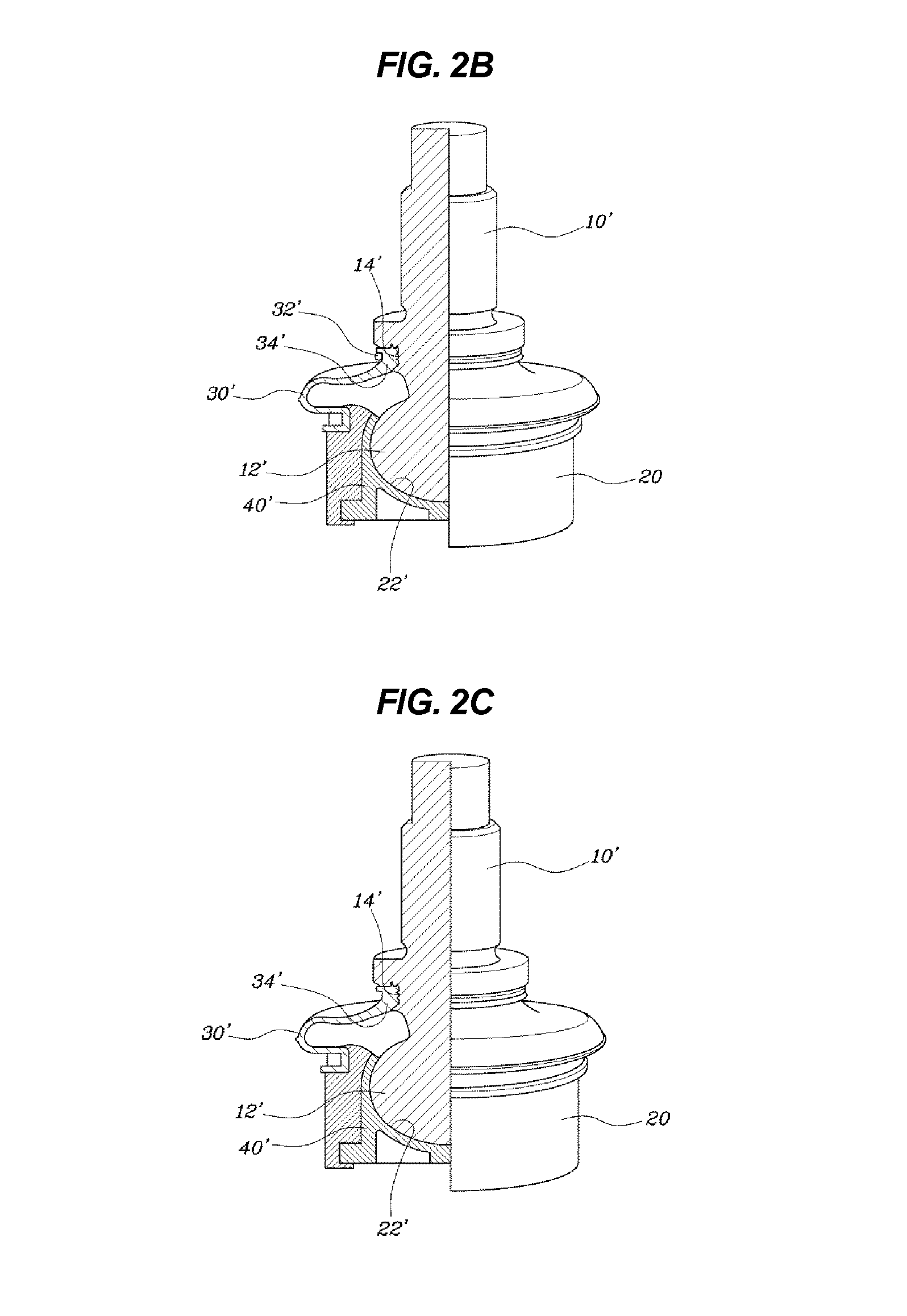
A stabilizer link apparatus may include ball studs having balls at terminals thereof, a link having ball sockets at upper and lower ends thereof, the balls being rotatably accommodated in the ball sockets, dust covers assembled between circumferences of the ball sockets and middle sections of the ball studs, the dust covers preventing impurities from invading the ball sockets, and friction-providing unit engaged between the ball stud and the link, wherein the friction-providing unit provide predetermined amounts of rotating frictional resistance to the ball studs when the ball studs rotate with respect to the link such that the rotating frictional resistance of the ball stud at the lower end of the link is greater than the rotating frictional resistance of the ball stud at the upper end of the link.

Description

CROSS REFERENCE TO RELATED APPLICATION[0001]The present application claims priority to Korean Patent Application No. 10-2013-0161882, filed on Dec. 23, 2013, the entire contents of which is incorporated herein for all purposes by this reference.BACKGROUND OF THE INVENTION[0002]1. Field of the Invention[0003]The present invention relates to a stabilizer link, and more particularly, to a stabilizer link which is intended to structurally reduce the swaying of a lower part thereof during the operation of a vehicle such that tension in a dust cover is reduced, thereby improving sealing performance.[0004]2. Description of Related Art[0005]A stabilizer is a stabilization device that prevents the body of a vehicle from lurching to the right and left. Unlike a shock absorber which prevents the vehicle from oscillating in the vertical direction, the stabilizer prevents the vehicle body from swaying to the right and left.[0006]The stabilizer is connected to a strut via a stabilizer link, and c...

Claims


Application Information

Patent Timeline
Patent Type & Authority Patents(United States)
IPC IPC(8): B60G7/00B60G21/055F16C11/06
CPCB60G7/005B60G21/055B60G21/0551F16C11/068F16C11/0676F16C11/0695B60G2204/1224B60G2204/416B60G2206/11Y10T403/32737F16C11/0671B60G21/05F16C11/06
Inventor KIM, JAE HUN
Owner HYUNDAI MOTOR CO LTD
Learn More