
Electrical connector

a technology of electrical connectors and connectors, which is applied in the direction of electrical apparatus, connection, and coupling device connection, etc., can solve the problems of reducing the service life of the connector, reducing the product yield, and trouble for users, so as to increase the thickness, reduce the use of metal materials, and increase the structural strength of the board-end connectors

Active Publication Date: 2016-04-05
ADVANCED CONNECTEK INC
View PDF10 Cites 5 Cited by
  • Summary
  • Abstract
  • Description
  • Claims
  • Application Information

AI Technical Summary

Benefits of technology

The solution increases product yield and service life, reduces damage from improper forces, and lowers manufacturing costs by utilizing less metal material while maintaining structural integrity for repeated connections.

Problems solved by technology

Consequently, the existing board-end connector 6 is liable to be damaged upon an improper force is applied, so that the service life of the connector may be reduced, thus causing troubles to users.
Besides, since the molding cavity for the insulation body 61 of the connector is too narrow, bubbles are liable to form in the insulation body 61 during the molding process, thereby reducing the product yield.
Also, since the metal support 63 with a large flat plate 632 requires more metal material, the manufacturing cost of the connector will be increased.
Therefore, an improper force may cause damages to the insulation body 61, thereby decreasing the product yield and thus affecting the cost reduction.

Method used


Image

  • Electrical connector
  • Electrical connector
  • Electrical connector

Examples


Embodiment Construction

[0021]The following paragraphs will illustrate a preferred embodiment with reference to the accompanying drawings to demonstrate the technical contents, features, and merits of the present invention. In the preferred embodiment, same elements will be indicated by similar reference numerals.

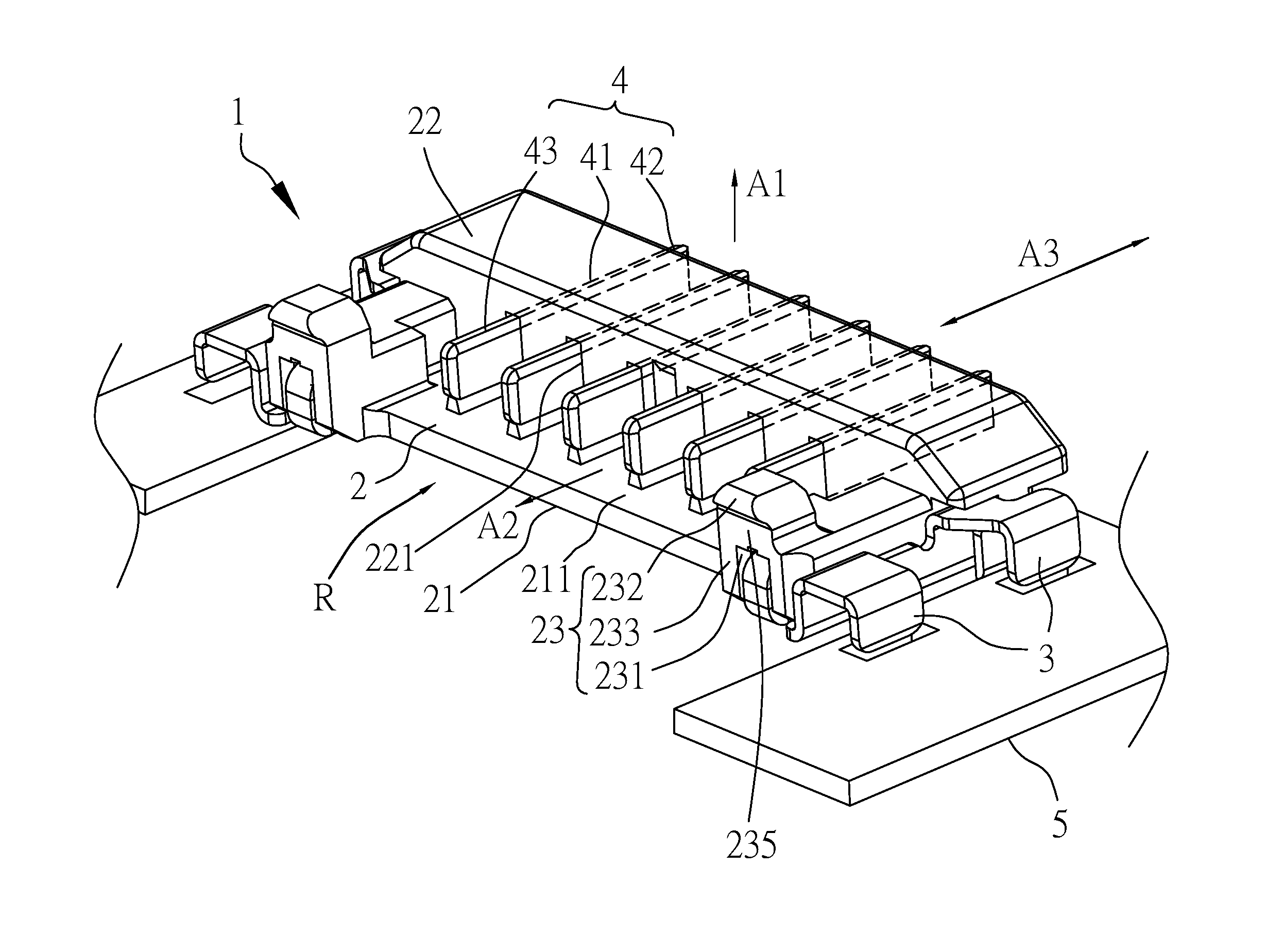
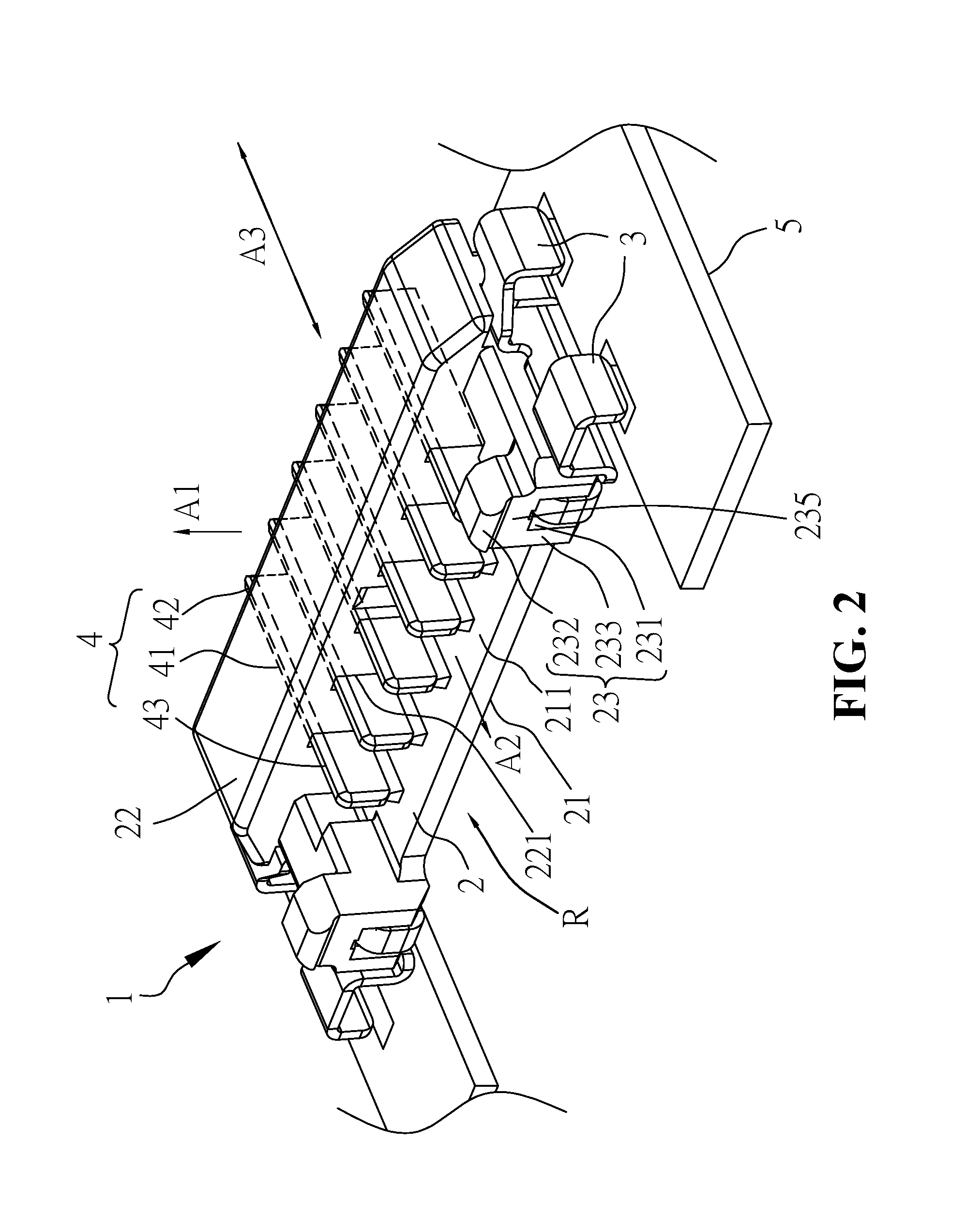
[0022]Referring to FIGS. 2 through 4, a board-end connector according to the preferred embodiment of the present invention is shown, which generally comprises an insulated housing 2, a pair of narrow metal brackets 3, and a plurality of conductive contacts 4. The insulated housing 2 is made of dielectric material, which is electrically insulated under general household voltage and current. In the embodiment, the insulated housing 2 is injection molded from plastic material having a dielectric characteristic.

[0023]The insulated housing 2 includes a connection plate 21, a raised portion 22 and two coupling portions 23. The connection plate 21, the raised portion 22 and two coupling portions 23 toget...


PUM


Abstract

An electrical connector for a circuit board includes an insulated housing, two narrow metal brackets, and a plurality of conductive contacts. The insulated housing has a connection plate, a raised portion, and two coupling portions at two opposite sides of the raised portion. The raised portion defines a plurality of contact grooves. Each coupling portion is formed in front of the raised portion. The two narrow metal brackets are provided for mounting with the coupling portions of the insulated housing. Each narrow metal bracket has a main plate, front and rear interference tabs for being interfered with one coupling portion of the insulated housing, and at least one positioning tab for being fixed onto the circuit board. The conductive contacts are fitted through the contact grooves of the raised portion.

Description

FIELD OF THE INVENTION[0001]The present invention relates to a board-end electrical connector to be mounted at a circuit board for connecting with a wire-end connector.BACKGROUND OF THE INVENTION[0002]Connectors are a component that provides electrical connection between different electronic devices or electronic components, so that electrical current or signal can be transmitted between the devices and thus enables the electronic devices or electronic components to communicate with each other. Since electronic devices or electronic components are usually separated at a certain distance, cables are required for communication therebetween. To facilitate a connection, each cable and its associated circuit board need to facilitate a connection therebetween by a wire-to-board connector. Generally, the wire-to-board connector includes a wire-end connector and a board-end connector. The wire-end connector includes a plurality of wire-end contacts and a wire-end housing that holds the plur...

Claims


Application Information

Patent Timeline
Patent Type & Authority Patents(United States)
IPC IPC(8): H01R12/79H01R12/75H01R12/70H01R13/639H01R13/518
CPCH01R12/75H01R12/707
Inventor CHEN, CHING-TIENDUAN, SHU-LINWAN, WEICHU, PING-CHUANQI, XIAO-JUAN
Owner ADVANCED CONNECTEK INC
Learn More