
Patient warming system

a patient and heating system technology, applied in the field of patient warming systems, can solve the problems of exacerbated problems, difficulty in providing warm air conduits from the heater to the patient, and warmed air heating systems, and achieve the effect of convenient connection

Active Publication Date: 2016-04-12
DUNLOP COLIN
View PDF17 Cites 5 Cited by
  • Summary
  • Abstract
  • Description
  • Claims
  • Application Information

AI Technical Summary

Benefits of technology

Enables efficient and flexible delivery of conditioned air across barriers, maintaining air flow without requiring conduit width adjustments and allowing for easy opening and closing of cage doors, ensuring patient warmth without disrupting the blanket's position.

Problems solved by technology

Where an animal needs to be warmed during care, in the cage, this leads to a problem in using warmed air heating systems.
There is therefore difficulty in providing the warm air conduit from the heater to the patient through the cage.
This problem is exacerbated by the fact that there are many different types of cages provided for veterinary patients, which, for example, have different diameters of bars, different grill patterns or grill widths for the cage and cage doors.
These problems prevent currently available hoses / piping providing heating conduits from being able to pass through a cage or cage door into a cage.
Generally, it is not convenient for the blanket to be moved once the patient is in the cage.
Having only one port, say at the head of the blanket, may make it difficult for the warm air to be provided to the blanket without moving it.
Having the port at the head end of the blanket (which is usually the case) in many cases, does not provide a convenient position for introducing the warmed air conduit to the port when the blanket arrangement is positioned within a cage.
As discussed above, trying to pass warmed air from a forced warmed air heating system via a conduit into the cage is difficult.
The only option may be the cage door, which presents the further difficulty that the cage door must be able to be opened, sometimes quickly for urgent access.

Method used


Image

  • Patient warming system
  • Patient warming system
  • Patient warming system

Examples


Embodiment Construction

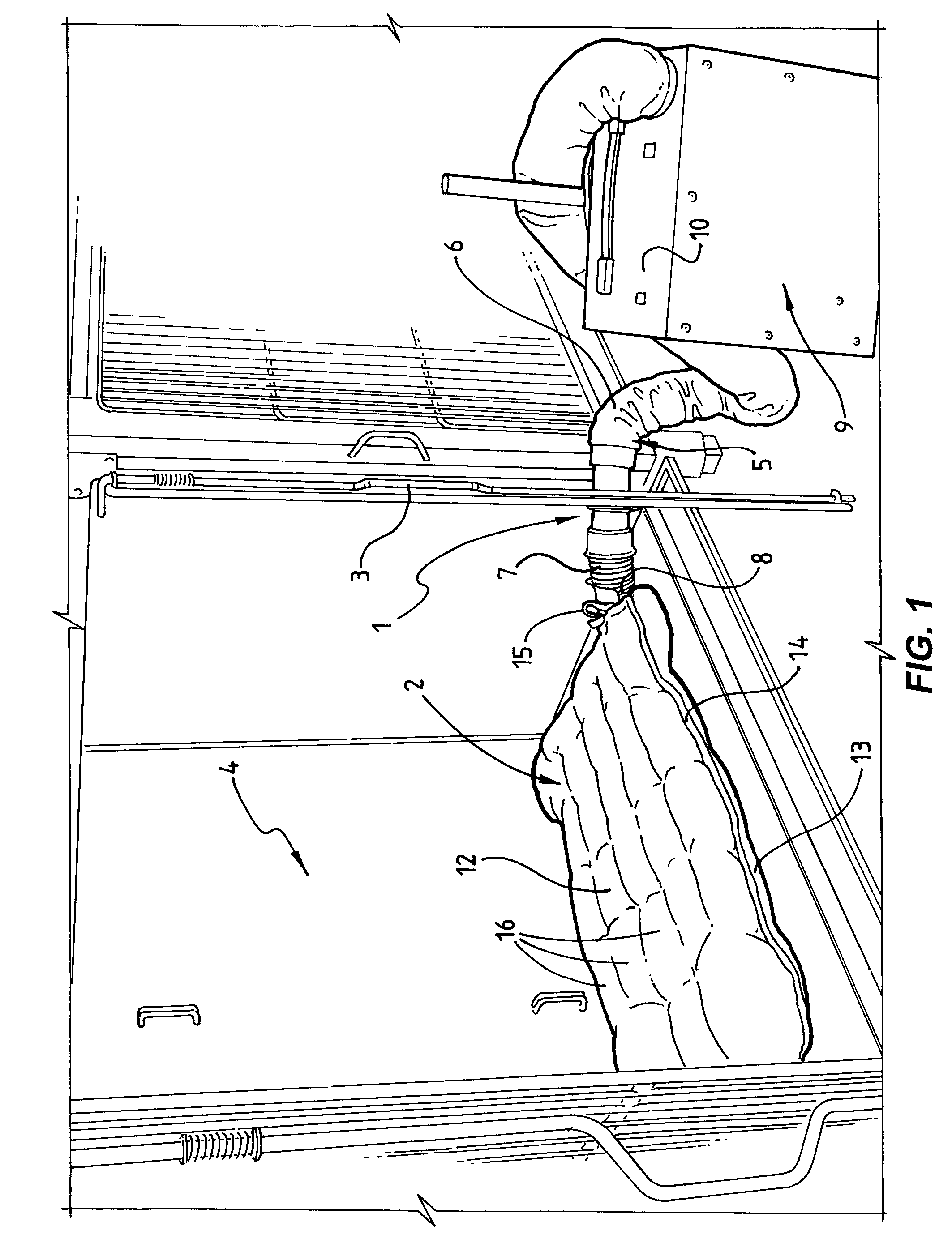
[0055]A system for providing conditioned air to a patient, in accordance with an embodiment of the present invention, is shown in FIG. 1.

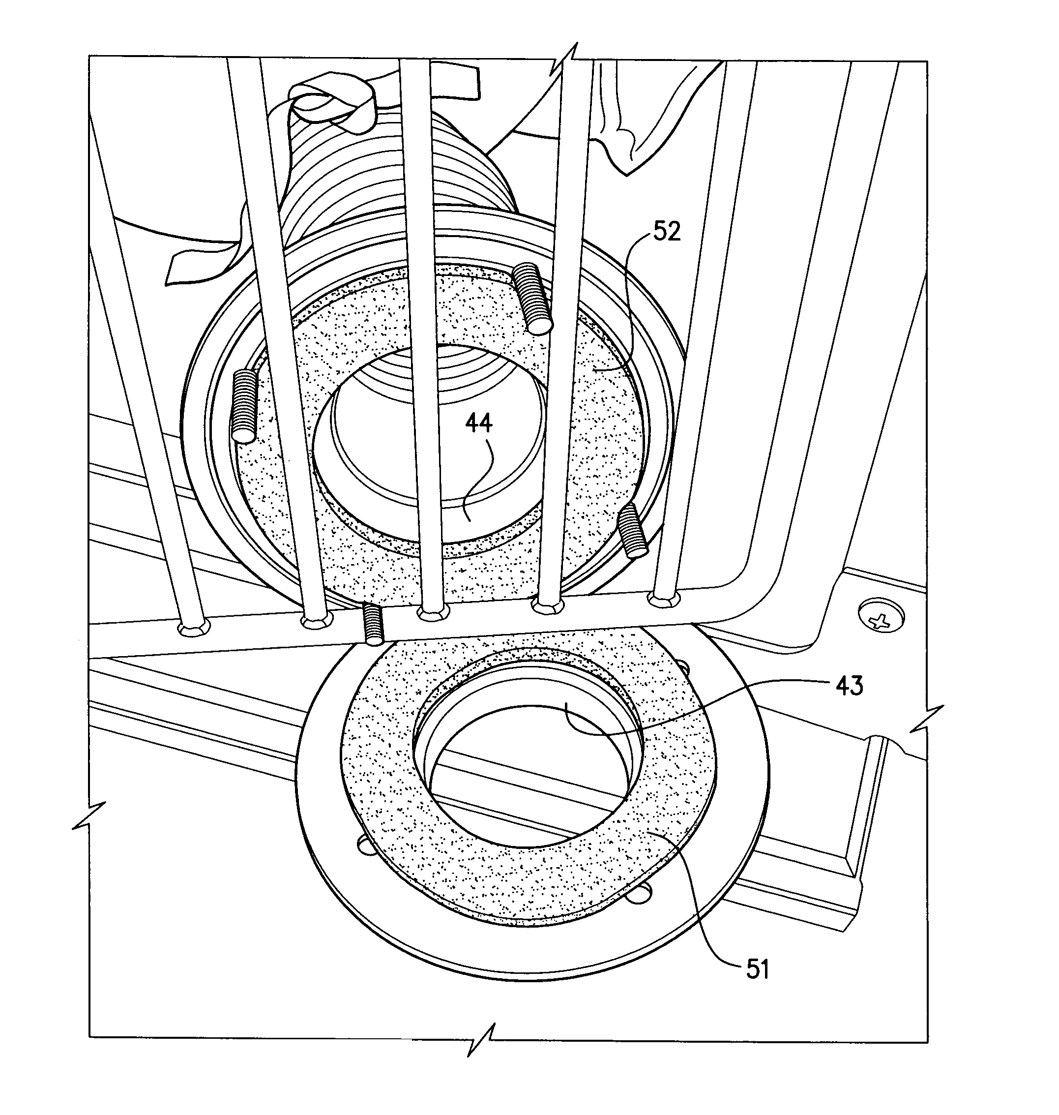
[0056]This embodiment comprises an apparatus, generally designated by reference numeral 1 for facilitating delivery of conditioned air (in this example warmed air) across a barrier to a blanket arrangement, generally designated by reference numeral 2. In this example embodiment, the barrier is the door 3 of a cage 4 arranged for containing an animal patient being treated. For example, the patient may be recovering from anaesthesia or surgery, or may be otherwise undergoing critical care.

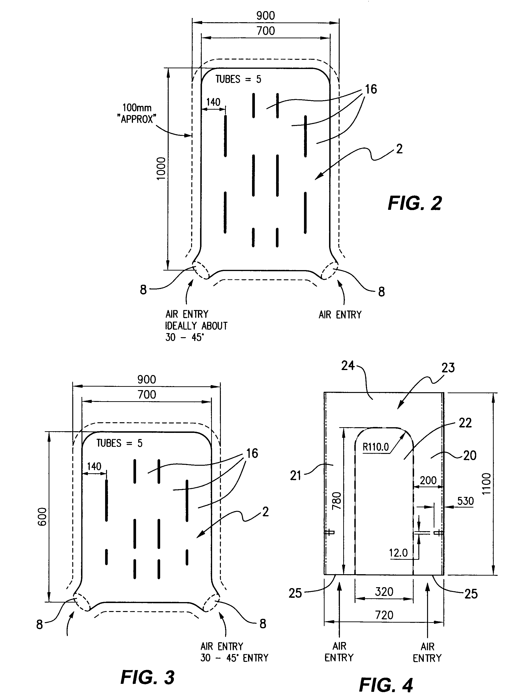
[0057]In this embodiment, the system comprises a conduit 5 for delivering warmed air to the blanket 2. The conduit 5 comprises a conduit part 6, outside the cage 4 and further conduit part 7 mounted inside the cage 4 and connecting to the blanket 2 via port 8. In this example, the apparatus 1 effectively connects the conduit part 6 and further conduit part 7 to faci...


PUM


Abstract

The present invention relates to a system for keeping a patient warm, particularly a veterinary patient, during care. An apparatus is provided for delivering conditioned air across a barrier, such as a wire cage, to a blanket arrangement for providing conditioned air to the patient. A first duct and a second duct part are provided either side of the barrier mounted together across the barrier, so a duct is provided for ducting conditioned air across the barrier.

Description

FIELD OF THE INVENTION[0001]The present invention relates generally to a system for keeping a patient warm during care and, more particularly, to an apparatus for delivering conditioned air across a barrier and a blanket arrangement for providing conditioned air to the patient, particularly, but not exclusively, for use in veterinary care.BACKGROUND OF THE INVENTION[0002]There are many circumstances in human and animal medicine where it is necessary to keep a patient warm to, for example, prevent or treat hypothermia. Forced warm air heating systems have been designed to keep patients warm during surgery and during critical care (e.g. recovery post-surgery).[0003]Forced warm air heating systems were originally designed for use in human medicine only, for the prevention and treatment of hypothermia during anaesthesia and in critical care. Primarily, the blankets were placed over patients recovering from anaesthesia. Recently blankets have been designed to provide warm air heating for...

Claims


Application Information

Patent Timeline
Patent Type & Authority Patents(United States)
IPC IPC(8): A61F7/08A61D3/00A61F7/00
CPCA61F7/08A61D3/00A61F7/0097A61F7/086A61F2007/006A61F2007/0091A61F2007/0055
Inventor DUNLOP, COLIN
Owner DUNLOP COLIN
Learn More