Dual-shaft synchronous transmission fixing device

a synchronous transmission and fixing device technology, applied in the direction of instruments, door/window fittings, constructions, etc., can solve the problems of untrue operation, rollers and wires (or transmission belts) slipping or untrue operation, and increase the manufacturing cost, so as to enhance the smooth rotation of the link unit, the effect of reducing the volume and simplifying the structur

Active Publication Date: 2016-04-12
FIRST DOME
View PDF13 Cites 10 Cited by
  • Summary
  • Abstract
  • Description
  • Claims
  • Application Information

AI Technical Summary

Benefits of technology

[0010]It is therefore a primary object of the present invention to provide a dual-shaft synchronous transmission fixing device, which has a simplified structure and minified volume. The gap between the rotary shafts can be changed or adjusted according to the transmission specification so that the electronic device can be thinned and lightweight. The dual-shaft synchronous transmission fixing device includes a driver disposed on a first shaft and a reactor disposed on a second shaft and a link unit engaged with the driver and the reactor, whereby the first and second shafts can be synchronously rotated in reverse directions. The dual-shaft synchronous transmission fixing device further includes a main fixing plate and a subsidiary fixing plate having identical structures. The main fixing plate and the subsidiary fixing plate are disposed on the first and second shafts. Each of the main fixing plate and the subsidiary fixing plate has a base section for together pivotally connecting with the link unit so as to enhance the smoothness of rotation of the link unit and avoid the problems of skip and idling of the conventional synchronous transmission mechanism.
[0011]In the above dual-shaft synchronous transmission fixing device, each of the base sections of the main fixing plate and the subsidiary fixing plate has a first section and a second section. The first section of the main fixing plate is correspondingly assembled with the second section of the subsidiary fixing plate, while the second section of the main fixing plate is correspondingly assembled with the first section of the subsidiary fixing plate. The base sections of the main fixing plate and the subsidiary fixing plate are formed with grooves. A lubricant or the like can be filled in the grooves to keep the link unit more smoothly rotated between the base sections.

Problems solved by technology

Basically, according to the above structural design and assembling process, the assembling time cannot be shortened so that the manufacturing cost is increased.
As known by those who are skilled in this field, during the operation process of the wires or the transmission belts, delay of kinetic energy transmission will take place.
This is because there is a gap between the wires (or transmission belts) and the rollers and the wires (or transmission belts) will slip or untruly operate.
Also, the wires (or transmission belts) are made of elastic material and the fixing structure for assembling the wires (or transmission belts) with the rollers is not ideal.
In this case, the transmission and shift effect of the wires will be deteriorated.
Also, the force of the wires or transmission belts, which is preset in the initial assembling process will decrease due to elastic failure.
Under such circumstance, the synchronous movement effect of the transmission mechanism will be deteriorated.
However, as known by those who are skilled in this field, with the transmission gears, the gap between the shafts of the dual-shaft synchronous movement device can be hardly minified.
Therefore, the entire transmission unit or structure will occupy a considerably large space.
Especially, when the transmission unit is applied to a notebook or a miniaturized electronic device, the electronic device can hardly meet the requirement for lightweight and slimmed design.

Method used


Image

  • Dual-shaft synchronous transmission fixing device
  • Dual-shaft synchronous transmission fixing device
  • Dual-shaft synchronous transmission fixing device

Examples


Embodiment Construction

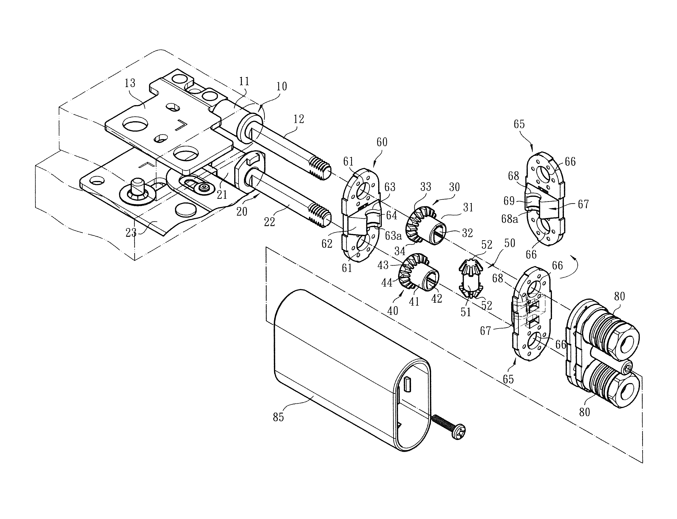
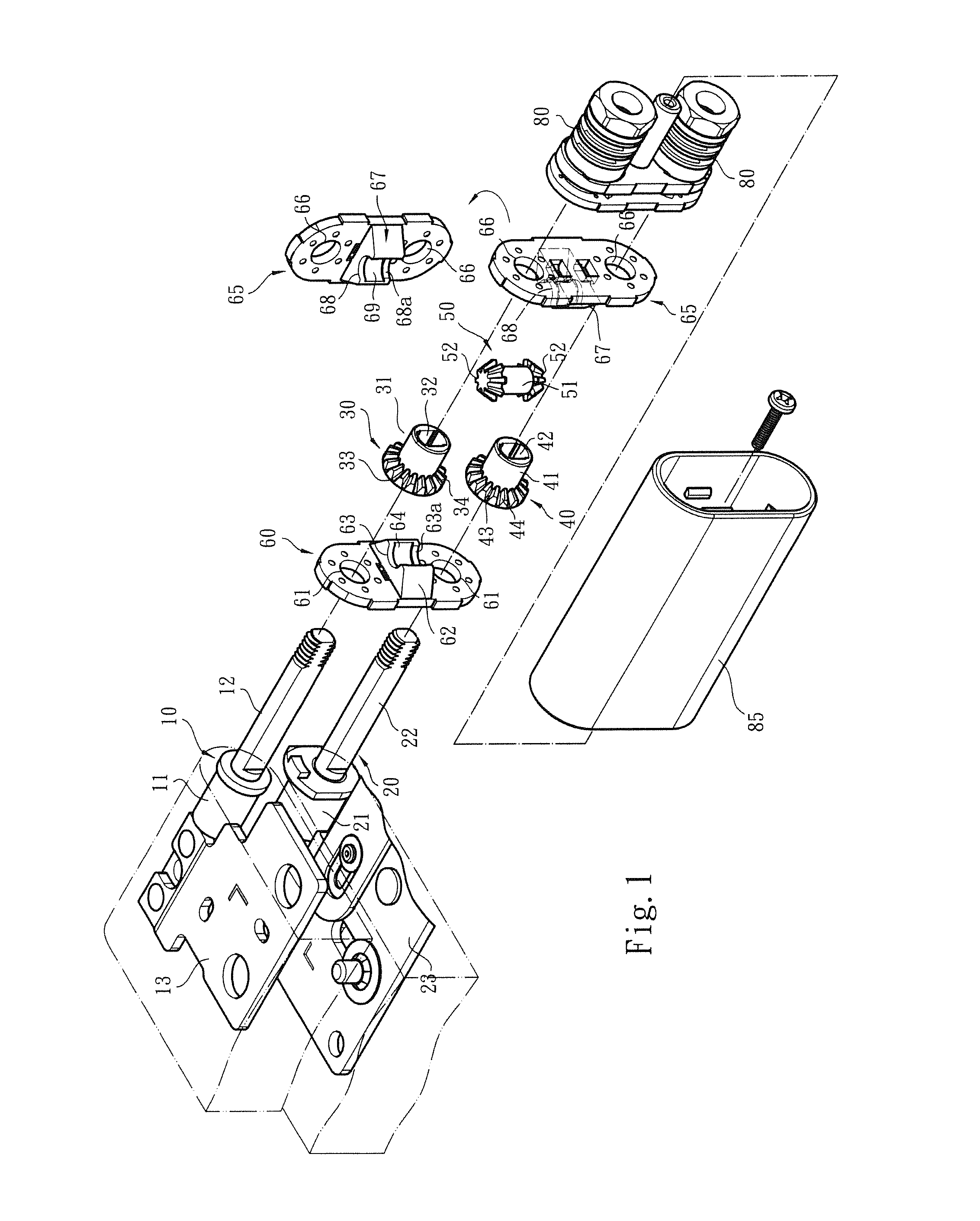
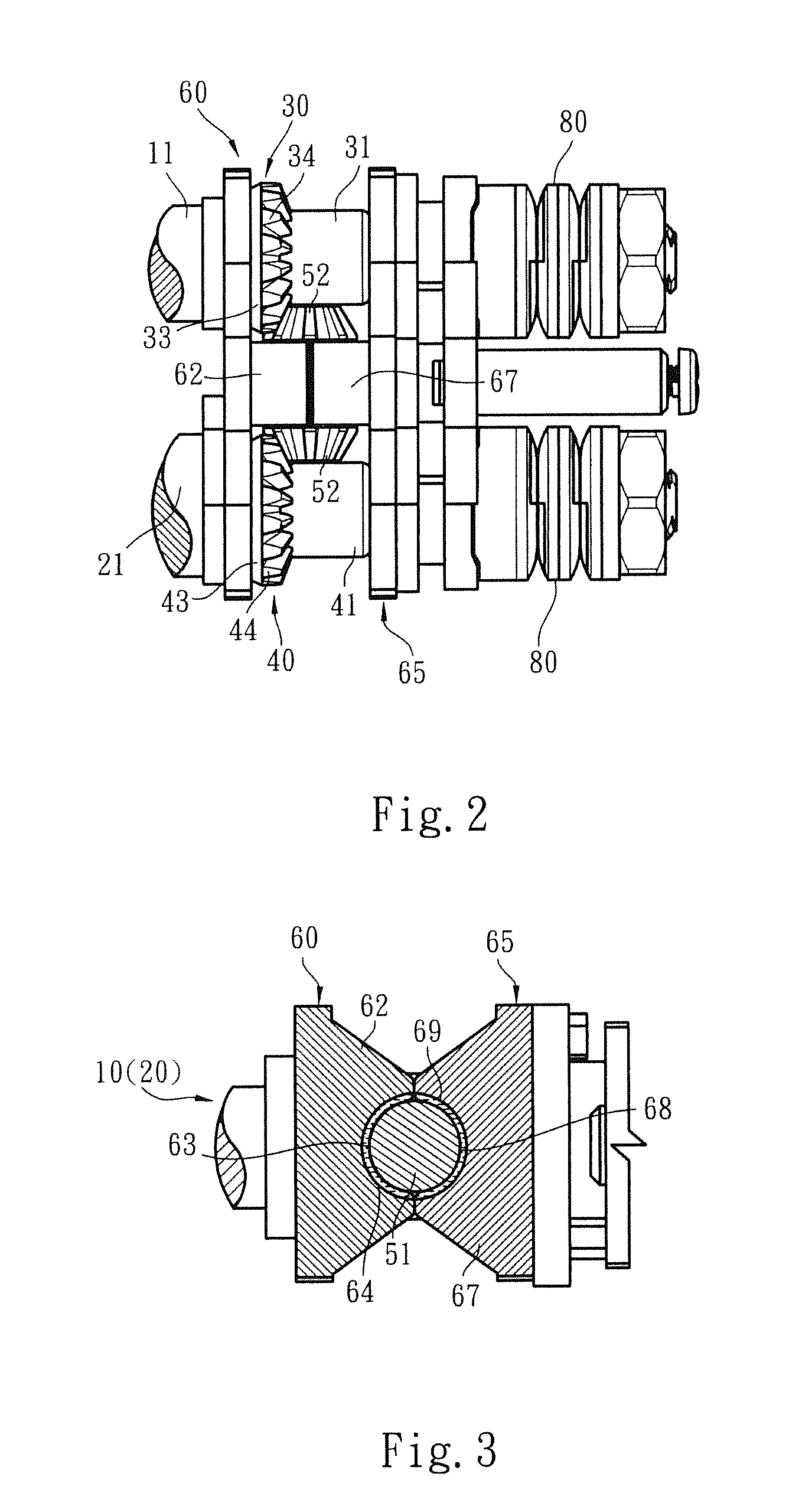
[0020]Please refer to FIGS. 1, 2 and 3. The dual-shaft synchronous transmission fixing device of the present invention includes a first shaft 10 and a second shaft 20. Each of the first and second shafts 10, 20 has a fixed section 11, 21 and a pivoted section 12, 22. The fixed sections 11, 21 are assembled with fixing seats 13, 23 to respectively fix the first and second shafts 10, 20 on a display module 91 and an apparatus body module 92 of an electronic apparatus 90 (such as a mobile phone, a computer or the like). The pivoted sections 12, 22 of the first and second shafts 12, 22 are (respectively) assembled with torque modules 80. Accordingly, when the action force applied to the display module 91 or the apparatus body module 92 by a user for rotating the same disappears, the display module 91 and the apparatus body module 92 are immediately located.

[0021]As shown in FIGS. 1, 2 and 3, a synchronous transmission device and a fixing device assembled with the synchronous transmissio...


PUM


Abstract

A dual-shaft synchronous transmission fixing device has a simplified structure and minified volume. The gap between the rotary shafts can be changed or adjusted according to the transmission specification so that the electronic device can be thinned and lightweight. The fixing device includes a driver and a reactor respectively disposed on a first shaft and a second shaft and a link unit engaged with the driver and the reactor, whereby the first and second shafts can be synchronously rotated. The fixing device further includes a main fixing plate and a subsidiary fixing plate having identical structures. The main fixing plate and the subsidiary fixing plate are disposed on the first and second shafts. Each of the main fixing plate and the subsidiary fixing plate has a base section for together pivotally connecting with the link unit.

Description

BACKGROUND OF THE INVENTION[0001]1. Field of the Invention[0002]The present invention relates generally to a dual-shaft synchronous transmission fixing device, and more particularly to a fixing device having a main fixing plate and a subsidiary fixing plate, which are assembled with the transmission mechanism to securely fix the transmission mechanism for stably transmitting power.[0003]2. Description of the Related Art[0004]There are various electronic apparatuses provided with covers or display screens, such as mobile phones, notebooks, PDA, and electronic books. The covers or display screens are pivotally mounted on the electronic apparatuses via pivot pins or rotary shafts, whereby the covers or display screens can be freely rotated and opened / closed under external force.[0005]In order to operate the display module (such as the screen) and / or the apparatus body module of the electronic apparatus in more operation modes and application ranges, a dual-shaft mechanism is provided b...

Claims


Application Information

Patent Timeline
Patent Type & Authority Patents(United States)
IPC IPC(8): E05D7/00E05D3/06E05D3/12G06F1/16
CPCE05D3/122G06F1/1681
Inventor HSU, AN SZULEE, WANG JUILIN, CHUNG YILIN, YA CHING
Owner FIRST DOME
Why Eureka
Try Eureka