
Piston arrangement for a combustion chamber of an internal combustion engine, having a variable compression ratio

a technology of compression ratio and piston arrangement, which is applied in the direction of engine controllers, machines/engines, pistons, etc., can solve the problems of complex adjustment of piston height and compression ratio, high proportion of identical parts, and high cost of installation and space, so as to achieve simple and therefore cost-effective and installation space-saving, efficient operation, and change the compression ratio of the combustion chamber

Inactive Publication Date: 2016-04-12
DAIMLER AG
View PDF18 Cites 1 Cited by
  • Summary
  • Abstract
  • Description
  • Claims
  • Application Information

AI Technical Summary

Benefits of technology

The present invention is about a piston arrangement for a combustion chamber with variable compression ratio. The arrangement allows for a simple and cost-effective adjustment of the compression ratio, which can suit different operating points of the internal combustion engine. The device is compact and has a high proportion of identical parts, reducing low-cost installation space. A control element can be moved on the piston, allowing for the adjustment of the compression ratio through centrifugal or inertial forces. This arrangement provides a better engine performance with low fuel consumption.

Problems solved by technology

It has been shown that adjustments of the piston height of this kind and therefore of the compression ratio are intricate.
Further, the piston arrangement is not only highly compact but also has a very high proportion of identical parts compared with a conventional piston arrangement that does not allow the compression ratio to be adjusted.

Method used


Image

  • Piston arrangement for a combustion chamber of an internal combustion engine, having a variable compression ratio
  • Piston arrangement for a combustion chamber of an internal combustion engine, having a variable compression ratio
  • Piston arrangement for a combustion chamber of an internal combustion engine, having a variable compression ratio

Examples


Embodiment Construction

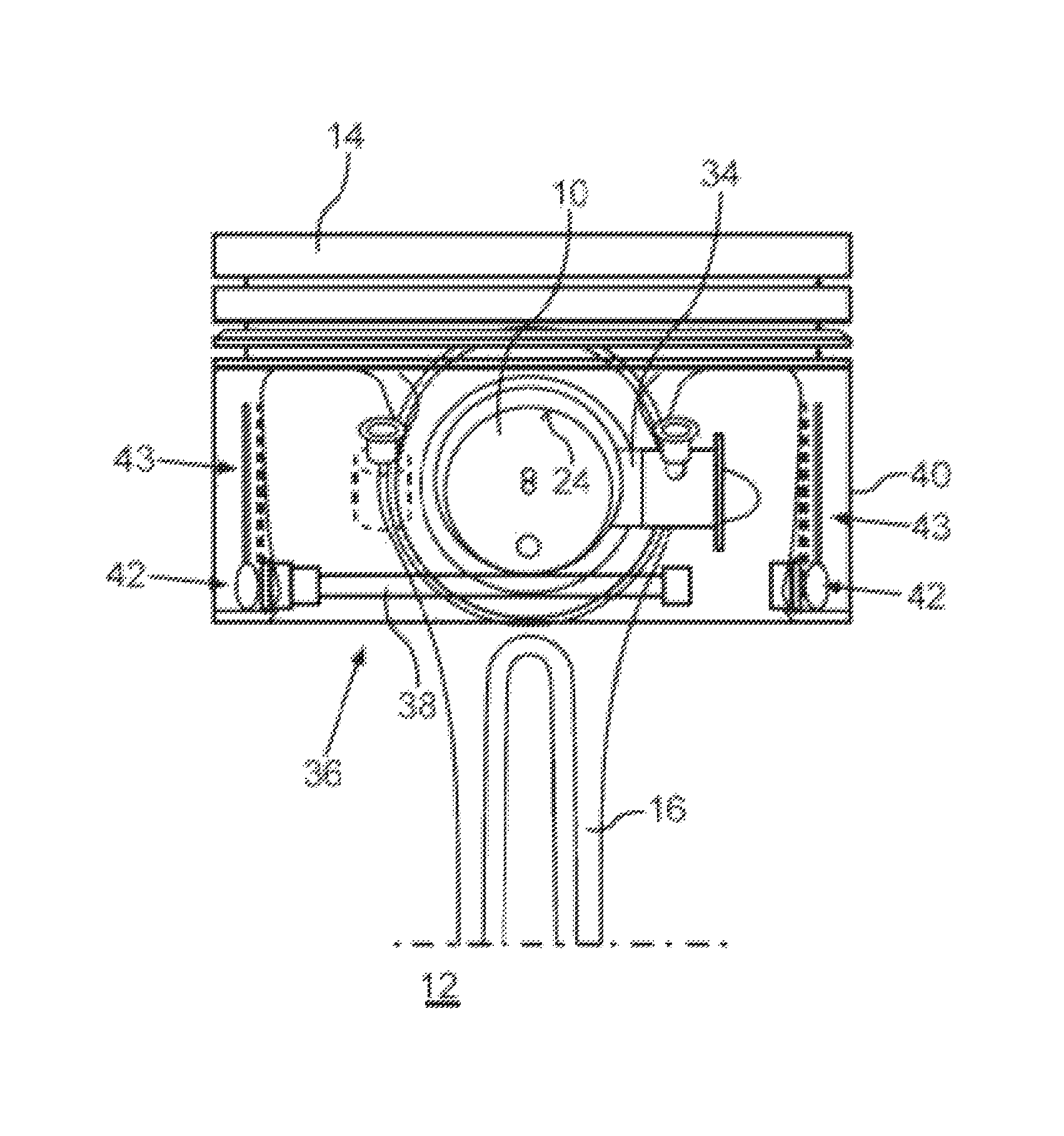
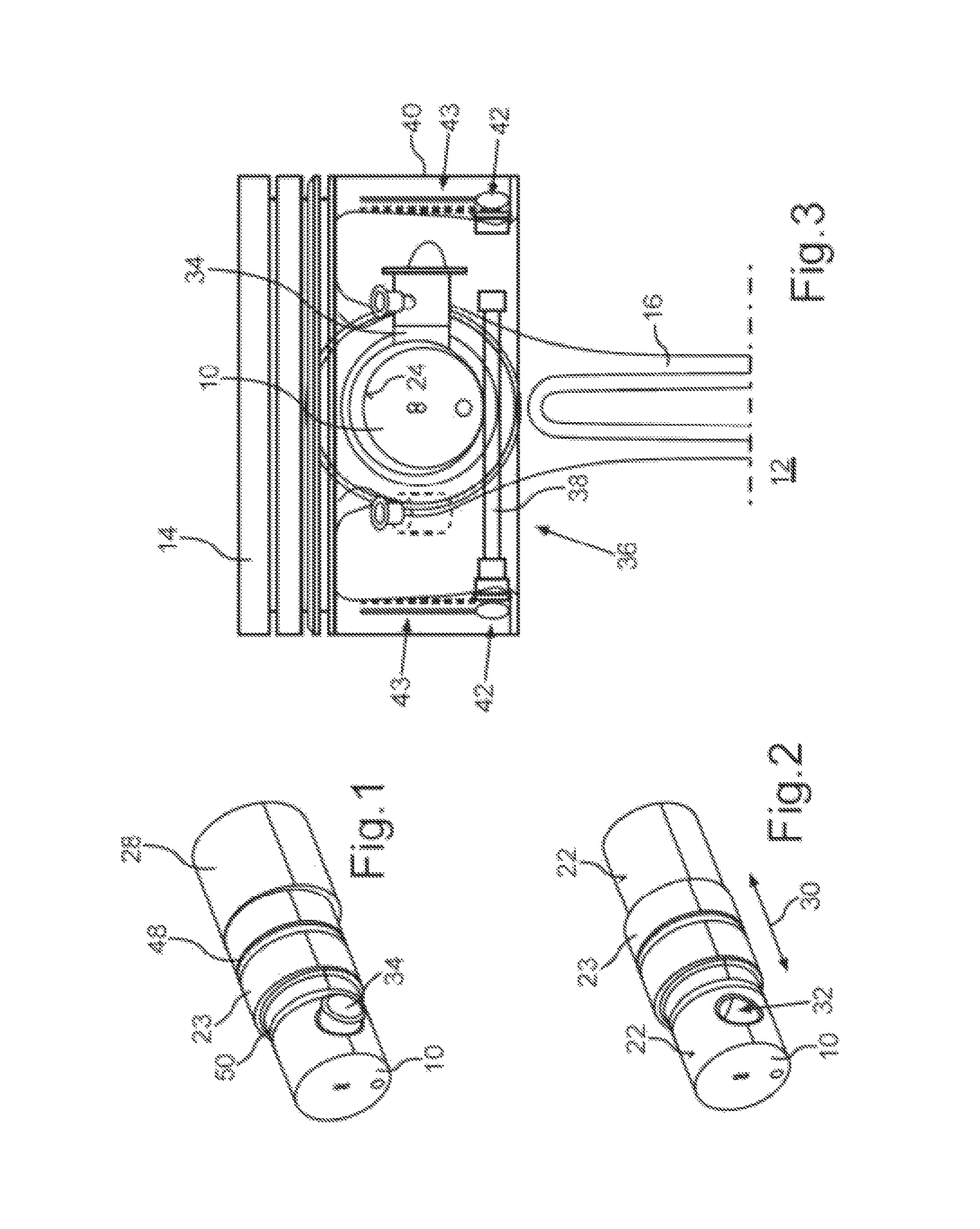
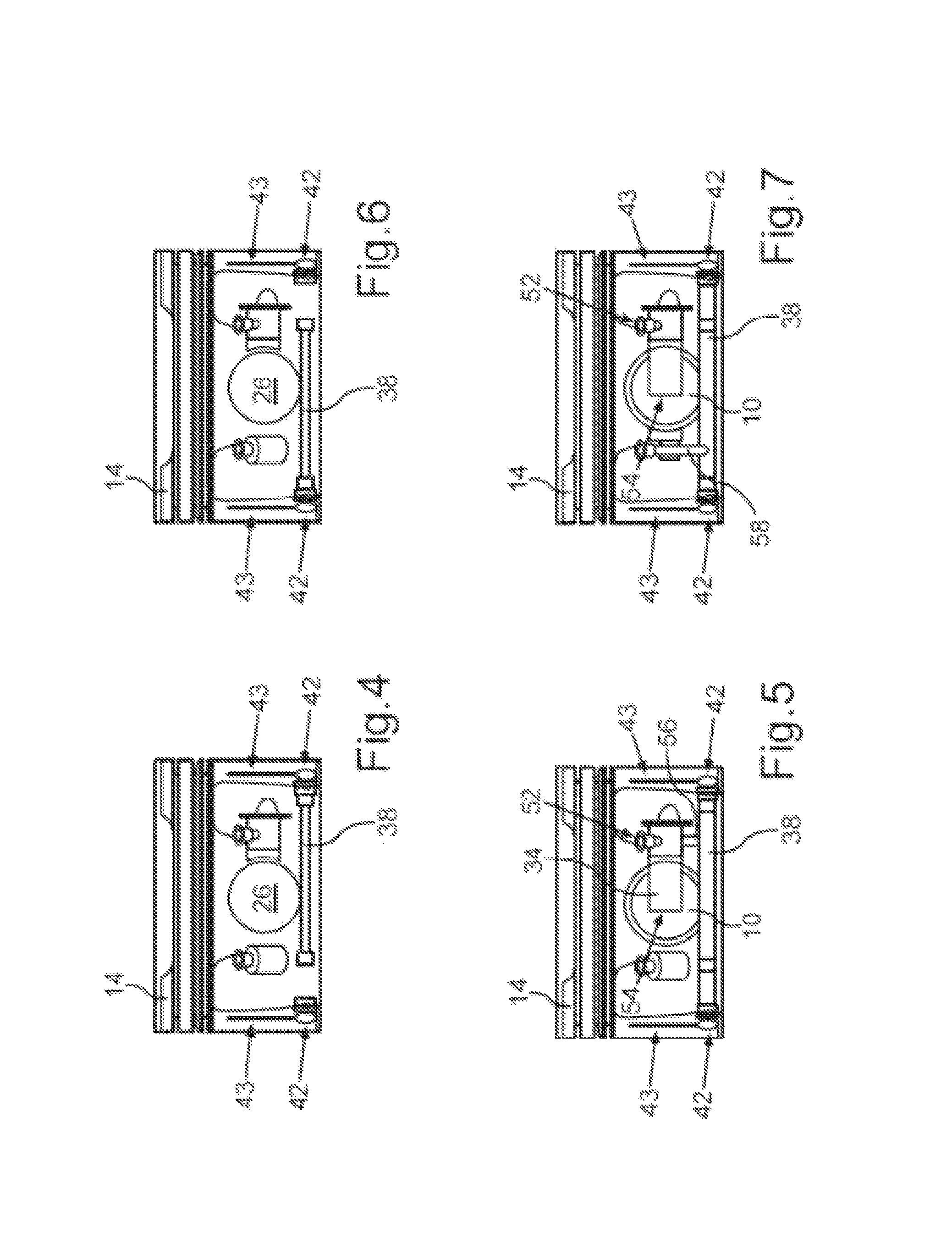
[0032]FIGS. 1 and 2 show a piston pin 10 of a piston arrangement 12 (FIG. 3), via which a piston 14 of the piston arrangement is to be coupled in an articulated manner to a connecting rod 16 of an internal combustion engine designed as a reciprocating piston internal combustion engine. As can be seen in conjunction with FIG. 8a-e, the internal combustion engine includes a crankshaft 18 mounted in a crankcase such that same can be rotated relative to the crankcase about an axis of rotation 20. The crankshaft 18 includes a crank pin, on which the connecting rod 16 is mounted in an articulated manner via a large connecting rod end. The connecting rod 16 further includes a connecting-rod small end in which the piston pin 10 is accommodated in some areas.

[0033]The piston pin 10 is coupled to the piston 14 via respective connecting regions 22. The connecting regions 22 of the piston pin 10 are formed by an outer peripheral lateral surface of the piston pin 10, wherein the connecting regio...


PUM


Abstract

A piston arrangement for a combustion chamber of an internal combustion engine having a variable compression ratio. A piston includes a device for the variable adjustment of the compression ratio associated with the combustion chamber, and a piston pin is coupled to the piston via respective connecting regions, via which piston pin the piston can be coupled to a connecting rod of the internal combustion engine. The device includes the piston pin having at least one eccentric element, which is eccentrically arranged with respect to the connecting regions of the piston pin and via which the piston pin can be coupled to the connecting rod.

Description

BACKGROUND AND SUMMARY OF THE INVENTION[0001]Exemplary embodiments of the invention relate to a piston arrangement for a combustion chamber of an internal combustion engine having a variable compression ratio.[0002]German patent document DE 33 46 967 C2 discloses a plunger piston having variable compression height for internal combustion engines, in which the piston crown is arranged in a relatively axially displaceable manner with at least one part of the piston ring section on the lower part which accommodates the piston pin. In the plunger piston, two interconnected chambers are provided which can be filled with pressure oil, and the respective volumes of which change with respect to one another in reciprocal proportion upon relative displacement of the piston crown, and of which a first chamber as control chamber lies directly below the piston crown, while a second chamber as damping chamber is arranged below the control chamber. Furthermore, in the piston, the pressure oil is c...

Claims


Application Information

Patent Timeline
Patent Type & Authority Patents(United States)
IPC IPC(8): F02D15/02F02B75/04F02F3/00
CPCF02B75/044F02B75/045F02D15/02F02F3/0069
Inventor NOWAK, DIETERROEMHELD, TILMANNWAGENPLAST, MICHAEL
Owner DAIMLER AG
Learn More