Heat treatment device for optical fiber reinforcing member, optical fiber fusion splicer provided with same heat treatment device, and method for heat treating optical fiber reinforcing member
a technology of heat treatment device and heating temperature, which is applied in the direction of optical elements, instruments, electrical appliances, etc., can solve the problems of increasing the amount of power consumed by the heater, reducing the amount of heat generated by the heater per unit time, and increasing the time to reach a desired heating temperature. , to achieve the effect of optimizing the heating condition
- Summary
- Abstract
- Description
- Claims
- Application Information
AI Technical Summary
Benefits of technology
Problems solved by technology
Method used
Image
Examples
example 1
[0040]Table I shows a result of examples where the reinforcing member 200 covering the fusion-spliced portion 110 was heated and shrunk by the heating device 10.
[0041]
TABLE IHeating conditionsHeatingNaturalForcibleTctcTstscoolingcoolingV(V)(° C.)(s)(° C.)(s)tn (s)tf (s)tr (s)Compar-13.8230523013529.15ative11.838.12example 111.047.910.079.069.097.28Example 113.82305230130529.1511.823023038.1211.021521535.410.020020036.169.018518538.029.016016088041.95 to47.19
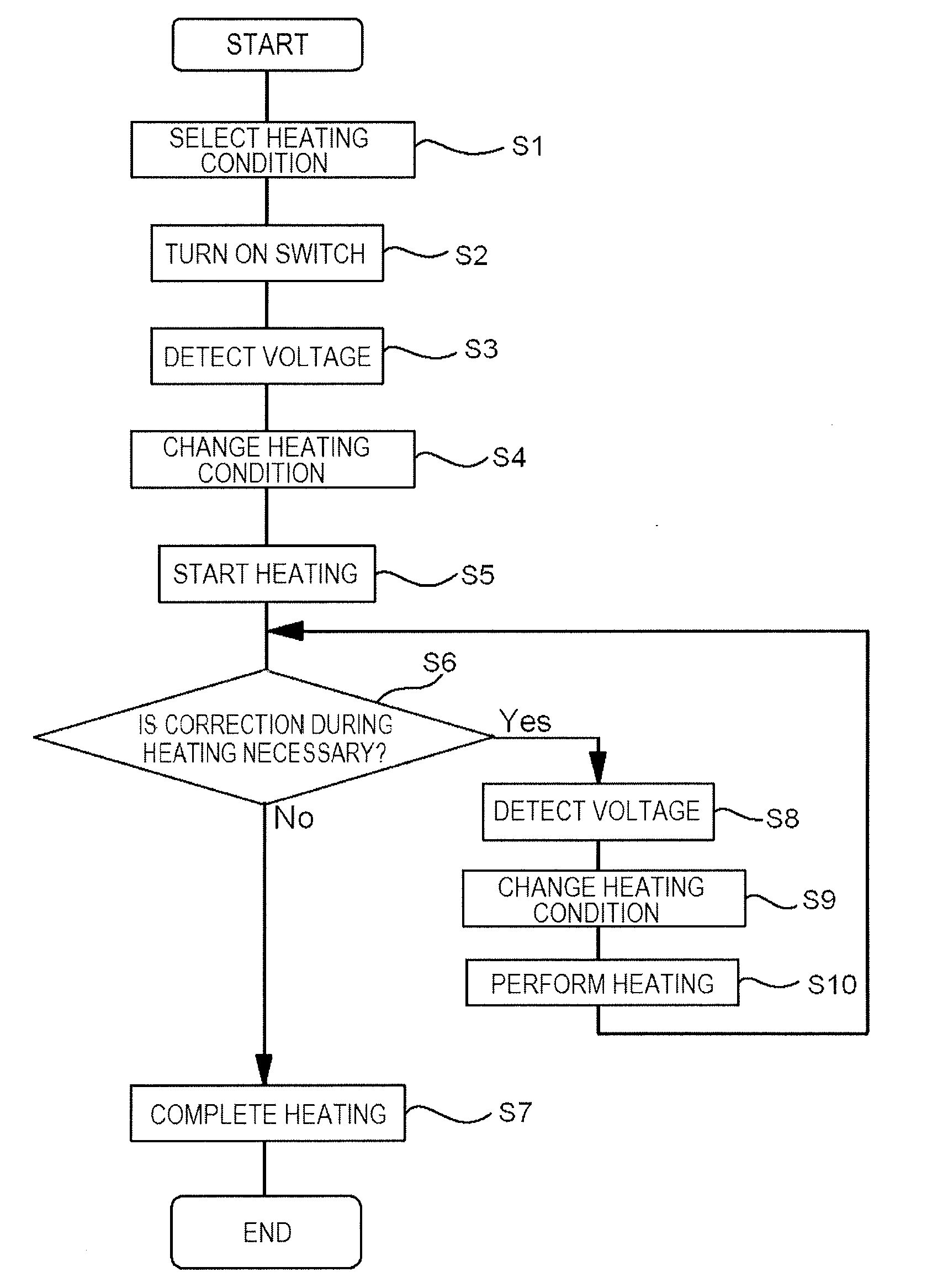
[0042]In comparative example 1, although a voltage V applied to the heating device 10 was varied from 9 V to 13.8 V, the optimization of the heating condition for heating the heater 12 (including a heating temperature Tc for heating a central portion, a voltage application period tc for applying a voltage to the central portion after the temperature Tc was reached, a heating temperature Ts for heating both end portions, a voltage application period ts for applying a voltage to both the end portions after the temperature Ts was re...
example 2
[0045]Next, an evaluation test similar to that for the reinforcing member 200 was performed using the fusion-spliced portion 110 covered with a reinforcing member 300. The reinforcing member 300 has dimensions different from those of the reinforcing member 20. The test result is shown in Table II.
[0046]
TABLE IIHeating conditionsHeatingNaturalForcibleTctcTstscoolingcoolingV(V)(° C.)(s)(° C.)(s)tn (s)tf (s)tr (s)Compar-13.82301221013533.41ative11.838.47example 211.045.9310.065.119.085.94Example 213.823012210130533.411.8230122101338.4711.0225132051444.4610.0215142001551.449.0205151951663.08
[0047]In comparative example 2, although the supply voltage of a battery connected to the heating device 10 was varied from 9 V to 13.8 V as in comparative example 1, the heating condition for the reinforcing member 300 was the same regardless of the voltage. As a result, in comparative example 2, the heating and reinforcing period significantly increased as the supply voltage of the battery decrease...
example 3
[0049]An evaluation test was performed to examine the relationship between the number of heating operations and the level of battery drain when the fusion-spliced portion 110 covered with the reinforcing member 300 was heated and reinforced by the heating device 10 connected to a low-voltage battery. In comparative example 3, the heating condition previously used (heating temperature Tc: 230° C., voltage application period tc: 5 seconds, heating temperature Ts: 230° C., voltage application period ts: 13 seconds, and natural cooling period: 0 seconds) was used. In example 3, an optimum heating condition for the low-voltage battery (heating temperature Tc: 210° C., voltage application period tc: 5 seconds, heating temperature Ts: 210° C., voltage application period ts: 8 seconds, and natural cooling period: 5 seconds) was used. Table III shows the result. In Table III, “remaining battery power” indicates the amount of remaining power in percentage relative to the power of the battery ...
PUM
 Abstract
Description
Claims
Application Information
 - R&D
- Intellectual Property
- Life Sciences
- Materials
- Tech Scout
- Unparalleled Data Quality
- Higher Quality Content
- 60% Fewer Hallucinations
Browse by: Latest US Patents, China's latest patents, Technical Efficacy Thesaurus, Application Domain, Technology Topic, Popular Technical Reports.
© 2025 PatSnap. All rights reserved.Legal|Privacy policy|Modern Slavery Act Transparency Statement|Sitemap|About US| Contact US: help@patsnap.com


