Variable area fan nozzle with drive system health monitoring

a technology of drive system and fan nozzle, which is applied in the direction of pump control, non-positive displacement fluid engines, instruments, etc., can solve the problems of engine fan stall, blade flutter, engine fan stall, and/or compressor surge, etc., to achieve the effect of simple and cost-effectiv

Active Publication Date: 2016-04-19
ROHR INC
View PDF5 Cites 4 Cited by
  • Summary
  • Abstract
  • Description
  • Claims
  • Application Information

AI Technical Summary

Benefits of technology

[0008]Turbofan engine nacelles are disclosed that include a variable area fan nozzle (VAFN) system having drive system health monitoring. In many embodiments, the drive system health monitoring employs proximity sensors mounted to the engine nacelle to periodically verify that predetermined portions of a movable fan nozzle are positioned consistent with a stowed configuration of the fan nozzle. By periodically verifying (e.g., twice per flight) the position of the predetermined portions of the fan nozzle, the required system reliability of the VAFN system can be satisfied in a simple and cost effective manner.

Problems solved by technology

Reducing an engine's FPR can reach a practical limit, however, as a low FPR may not generate sufficient thrust and may cause engine fan stall, blade flutter, and / or compressor surge under certain operating conditions.
Such monitoring, however, should be sufficiently reliable, which may be difficult to achieve with VAFN systems having multiple components that are selectively repositioned relative to the nacelle via one or more actuation systems.

Method used


Image

  • Variable area fan nozzle with drive system health monitoring
  • Variable area fan nozzle with drive system health monitoring
  • Variable area fan nozzle with drive system health monitoring

Examples


Embodiment Construction

[0039]In the following description, various embodiments of the present invention will be described. For purposes of explanation, specific configurations and details are set forth in order to provide a thorough understanding of the embodiments. However, it will also be apparent to one skilled in the art that the present invention can be practiced without the specific details. Furthermore, well-known features may be omitted or simplified in order not to obscure the embodiment being described.

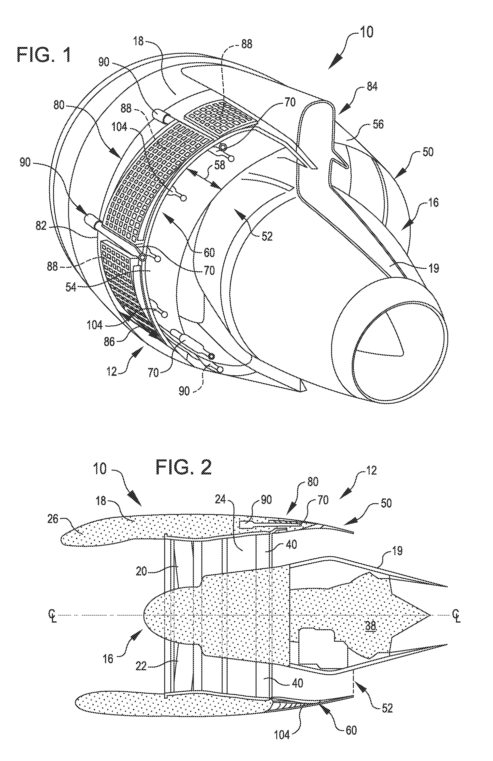
[0040]Referring now to the drawings, in which like reference numerals represent like parts throughout the several views, FIG. 1 shows a turbofan engine 10 that includes a variable area fan nozzle (VAFN) assembly 12 having a translating fan nozzle 50 that can be selectively adjusted, for example, as the engine 10 operates under different flight conditions. As discussed above, such an adjustment can be used to optimize the engine's performance. As shown in FIG. 2, the translating fan nozzle 50 can b...


PUM


Abstract

A nacelle for a turbofan engine includes a variable area fan nozzle (VAFN) and a proximity sensor that is attached to a nacelle forward portion to sense the presence of the VAFN when stowed. The proximity sensor is not attached to the VAFN, thereby enabling the use of a proximity sensor such as linear variable displacement transformer having a relatively compact operational stroke.

Description

BACKGROUND[0001]Typical aircraft turbofan jet engines include an engine core, a nacelle that surrounds the engine core, and a fan that draws in a flow of air that is split into bypass airflow and engine core airflow. The nacelle provides a bypass duct that surrounds the engine core. The bypass airflow is transported through the bypass duct. The nacelle is configured to promote laminar flow of air through the bypass duct. The engine core includes a multi-stage compressor to compress the engine core airflow, a combustor to add thermal energy to the compressed engine core airflow, and a turbine section downstream of the combustor to produce mechanical power from the engine core airflow. The typical turbine section has two and sometimes three turbine stages. The turbine stages are used to drive the compressor and the fan. After exiting from the turbine section, the engine core airflow exits through an exhaust nozzle at the aft end of the engine.[0002]In a turbofan engine, the fan typica...

Claims


Application Information

Patent Timeline
Patent Type & Authority Patents(United States)
IPC IPC(8): F01D17/02F02K1/15F02K1/09
CPCF01D17/02F02K1/09F02K1/15G08B21/18
Inventor SCANLON, KEVIN ROBERTPINTO, GEOFFREY
Owner ROHR INC
Why Eureka
Try Eureka