Tissue collection and refining device and method

a tissue collection and refining device technology, applied in the direction of liquid handling, suction drainage containers, transportation and packaging, etc., can solve the problems of inability to achieve, achieve the effect of improving processing methods, preventing the rotation movement of canisters, and facilitating viewing extraction and separation

Active Publication Date: 2016-04-26
SUMMIT MEDICAL LLC
View PDF19 Cites 11 Cited by
  • Summary
  • Abstract
  • Description
  • Claims
  • Application Information

AI Technical Summary

Benefits of technology

[0018]The canister itself has extended and flanged perimeter edges for reinforcement, stability and ease of use, with a small indentation opposite the funnel spout orifice for ease of mounting on its stand. On the bottom of the canister, gaps in the flanged edge provide two slot insertion points whereby there is a grip on the flange while also preventing rotating movement of the canister. A plate support resides under the bottom of the canister creating structural support, while still providing maximum available view of contents of the canister and elevation to provide easy access to the barbed spout.
[0019]In another feature of the present invention, the separator is in the form of an eccentric funnel with a downwardly extending barbed spout extending the tissue retrieval port outside of the canister body and providing an attachment surface for different types of tubing according to clinical need. The funnel has a specifically designed reinforced circumferentially barbed spout in the design of a hose barb, designed to fit and glue specifically within a similarly reinforced ring around the orifice through which the spout protrudes. In this way, the adhesive adheres specifically and most strongly to the spout itself, the strongest component of the funnel. In this way, the funnel if necessary can flex and move up and down as the canister flexes under vacuum, but the funnel does not lose its position at its strongest and most critical point. The eccentric funnel places the spout more proximal to the edge of the canister versus in the middle. Using this positioning, the users can more easily view the extraction and separation of tissue and fluid, and determine if there is a need to aspirate or plunge the more solid or clogging tissue. Previous designs do not allow this key visibility and thus greatly improved processing method, which also provides the desired alternative to not use tubing at all, but drain directly to another basin, as some surgeons prefer. Additionally, when tubing is attached to this spout and sometimes needs to be added or extracted, it can be done more easily and under visual control as it's near the peripheral edge of the canister. Presently in the field some surgeons have canisters on a table's edge, and place other containers under the spout. This has not been possible with the spout in the middle underneath the canister as with the prior art. In the inventive device, the placement of the spout on the outside edge makes container position more secure, more convenient, and more easily controlled.

Problems solved by technology

This has not been possible with the spout in the middle underneath the canister as with the prior art.

Method used


Image

  • Tissue collection and refining device and method
  • Tissue collection and refining device and method
  • Tissue collection and refining device and method

Examples


Embodiment Construction

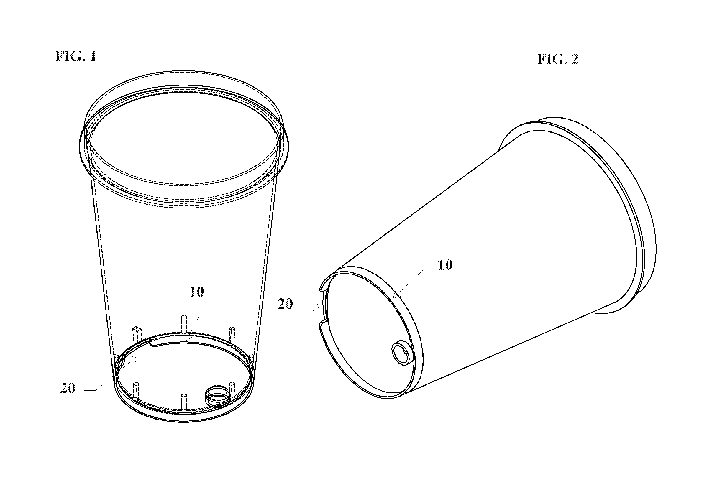
[0031]Regarding FIG. 1, the opaque representation of the tissue collection canister has extended and flanged perimeter edges 10 for reinforcement, stability and ease of use, with a small indentation 20 opposite the funnel spout orifice for ease of mounting. The canister itself is most often mounted on a stand for improved stability to elevate the funnel spout and the tubing attached to it. Alternatively, some surgeons like to place the canister on the edge of a table or similar plain, and let the fluid run out into another vessel. This has been a request of one of the foremost surgeons in the field, but has not be possible with the funnel spout in the middle bottom of the canister.

[0032]Regarding FIG. 2, the illustration is transparent in an effort to clearly show the extended and flanged perimeter edges 10 for reinforcement, stability and ease of use, with a small indentation 20 opposite the funnel spout orifice for ease of mounting. Prior art canisters have unreinforced circumfere...


PUM

PropertyMeasurementUnit
perimeteraaaaaaaaaa
flexibilityaaaaaaaaaa
areaaaaaaaaaaa

Abstract

A tissue refining device for collecting and processing tissue received from a harvesting device under suction from a vacuum source comprising an improved canister and separator device wherein the canister is reinforced to avoid cracking, an eccentric funnel is used to separate the space within the canister which also allows for visual inspection and control of the tissue, liquid, and fat. A specially designed barbed spout on the funnel allows for flex at that connection without loss of device integrity. The device also has a proprietary method for placement on its custom stand.

Description

FIELD[0001]The present invention relates to fluid and tissue collection devices and more specifically to devices for collecting and processing aspirated adipose tissue for use in autologous adipose tissue implantation procedures.BACKGROUND OF THE INVENTION[0002]Liposuction, a popular type of cosmetic surgery also known as lipoplasty, liposculpture and suction assisted body contouring, is a technique for removing adipose tissue by inserting a hollow tube, or canula, through the skin and connecting it to a vacuum pump to suction out a quantity of fatty tissue. The procedure may be used to remove unwanted deposits of excess fat, to improve body appearance, and to smooth irregular or distorted body shapes, also known as body sculpting. Liposuction may be useful for contouring almost any area of the body including under the chin, neck, cheeks, upper arms, breasts, abdomen, buttocks, hips, thighs, knees, calves, and ankle areas.[0003]A liposuction machine and special instruments are used ...

Claims


Application Information

Patent Timeline
Patent Type & Authority Patents(United States)
IPC IPC(8): A61M1/00A61M39/00G01N1/04A61B17/00B67C11/00
CPCG01N1/04A61M1/0007A61M1/0005A61M1/0056A61M1/0001A61M1/0023A61B2217/005A61M2202/08A61B2017/00969B67C11/00A61M2209/084A61M1/631A61M1/79A61M1/89A61M1/60A61M1/63
Inventor KIMSEY, II, MELBOURNE
Owner SUMMIT MEDICAL LLC
Why Eureka
Try Eureka