Fibre optic network design method

a fibre optic network and design method technology, applied in data switching networks, instruments, analogue processes for specific applications, etc., can solve the problems of adding to network costs, manually modifying the designed network to reduce the amount of infrastructure, or in response to changing requirements, and achieving the effect of minimising construction costs and reducing network construction costs

a fibre optic network and design method technology, applied in data switching networks, instruments, analogue processes for specific applications, etc., can solve the problems of adding to network costs, manually modifying the designed network to reduce the amount of infrastructure, or in response to changing requirements, and achieving the effect of minimising construction costs and reducing network construction costs

US9323872B2Active Publication Date: 2016-04-26BIARRI NETWORKS PTY LTD

Image

  • Fibre optic network design method
  • Fibre optic network design method
  • Fibre optic network design method

Examples


Embodiment Construction

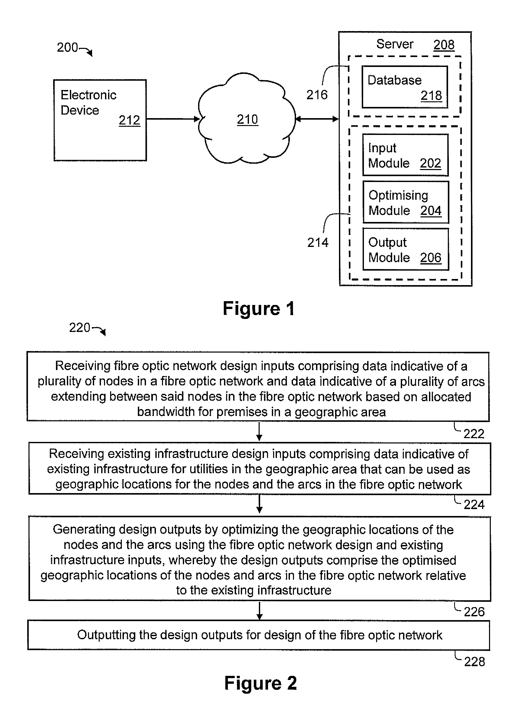
[0049]According to an embodiment of the present invention, there is provided a system 200, as shown in FIG. 1, for designing a fibre optic network for a plurality of premises in a geographic area, such as a suburb, comprising existing infrastructure for utilities in the suburb, such as infrastructure for a power network. The system 200 comprising an input module 202 arranged to receive fibre optic network design inputs comprising data indicative of a plurality of nodes in the fibre optic network and data indicative of a plurality of arcs extending between the nodes in the fibre optic network based on allocated bandwidth for premises in the suburb. The input module 202 is also arranged to receive existing infrastructure design inputs comprising data indicative of the existing infrastructure that can be used as geographic locations for the nodes and arcs in the fibre optic network. The system 200 further includes an optimising module 204 arranged to perform optimisation with respect t...


PUM


Abstract

A system and method of designing a fiber optic network for a plurality of premises in a geographic area that has existing infrastructure is described. They include electronically receiving fiber optic network design inputs that include data indicative of a plurality of nodes in the fiber optic network and data indicative of arcs extending between said nodes in the fiber optic network based on allocated bandwidth for said premises in the geographic area, electronically receiving existing infrastructure design inputs comprising data indicative of said existing infrastructure that can be used as geographic locations for said nodes and said arcs in the fiber optic network, electronically generating design outputs by optimizing geographic locations of said nodes and said arcs in the fiber optic network using said fiber optic network design inputs and said existing infrastructure inputs, and electronically outputting the design outputs.

Description

TECHNICAL FIELD[0001]The present invention relates to a method of designing a fibre optic network for a plurality of premises in a geographic area comprising existing infrastructure for utilities in the geographic area. This application is based on and claims the benefit of the filing date of Australian provisional patent application no. 2010903705 filed 18 Aug. 2010, the content of which, as filed, is incorporated herein by reference in its entirety.BACKGROUND[0002]Optical fibre can be used as a medium for telecommunication and networking because it is flexible and can be bundled as cables. It is especially advantageous for long-distance communications because light propagates through the fibre with little attenuation compared with electrical cables. In recent times, vast fibre optic networks have been commissioned to cope with the increasing growth in Internet communication and cable television.[0003]In one existing example, fibre optic networks are designed manually with a view o...

Claims


Application Information

Patent Timeline
26 Apr 2016
Publication
US9323872B2
IPC
G06F17/50; H04L12/24
CPC
G06F17/5009; H04L41/145; G06F17/509; G06F2217/36; G06F30/18; G06F30/20; G06F2113/16
Inventors
FORBES, MICHAEL; HOLLIS, BENJAMIN LESLIE