Method for controlling a working machine

a technology for working machines and electronic control units, applied in soil-shifting machines/dredgers, computations using stochastic pulse trains, non-denominational number representations, etc., can solve the problems of reducing the remaining power usable for the hydraulic system, the general challenge the traction system by controlling the gas pedal and hydraulic levers, and the difficulty of balancing the hydraulic system. , to achieve the effect of reducing the amount of fuel consumed

Active Publication Date: 2016-05-03
VOLVO CONSTR EQUIP AB
View PDF10 Cites 1 Cited by
  • Summary
  • Abstract
  • Description
  • Claims
  • Application Information

AI Technical Summary

Benefits of technology

[0024]The main advantage with an aspect of the present invention is that even inexperienced operators can operate a working machine more easily by preventing the lifting force from being totally cancelled out by the reaction force and making it achieved through the control of the engine speed according to the bucket state.
[0025]Another advantage of the present invention is that a working machine can be operated in a productive, yet fuel-efficient manner by eliminating unnecessary fuel consumption related to the bucket being stuck in the gravel pile and accordingly increasing the efficiency of the working machine during the bucket filling phase.
[0026]Other preferred embodiments and advantages of the invention will emerge from the detailed description below.

Problems solved by technology

Consequently, the operator is constantly challenged to balance the power given to the hydraulic system and the traction system by controlling the hydraulic levers (ex. lift and tilt levers of a wheel loader) and the gas pedal of the working machine.
This is a general challenge for the operator of a working machine in which the engine is used for powering both the hydraulic system and the traction system.
However, in contrast to a manual shovel, these three motions cannot be directly controlled by the operator of a wheel loader, in spite of being observed.
During a bucket filling phase, the general challenge of balancing the hydraulic system and the traction system by controlling the gas pedal and hydraulic levers becomes more complicated.
This is because the power delivered to the traction system does not only decrease the remaining power usable for the hydraulic system, but also directly prevent the lifting motion of the bucket due to a strong interaction between the forces originating from the two systems.
However, this will just make the situation worse: more traction force will be created, which counteracts the lifting effort even more and the working machine consumes fuel without any useful work.
The fact that the lifting force is cancelled out by traction in such a manner and the operator must do the counter-intuitive thing during the bucket filling phase yields several problems.
The working machine will be experienced as a weak machine and a machine of poor operability by the operator, especially by an inexperienced one, who will have a negative impression accordingly.
As the operability is poor, the operator will not be able to operate the machine in a productive, yet fuel-efficient manner.
This poor operability and lack of fuel efficiency are not the problems pertaining only to inexperienced operators.
The bucket can sometimes be stuck in the gravel pile even when the machine is operated by an experienced operator.
However, the unnecessary fuel consumption due to the situation that the bucket is stuck in the gravel pile is unavoidable.

Method used


Image

  • Method for controlling a working machine
  • Method for controlling a working machine
  • Method for controlling a working machine

Examples


Embodiment Construction

[0046]The invention will now be described in detail with reference to the preferred embodiments of the invention and the drawings. The embodiments of the invention with further developments described in the following are to be regarded only as examples and are in no way to limit the scope of the protection provided by the patent claims.

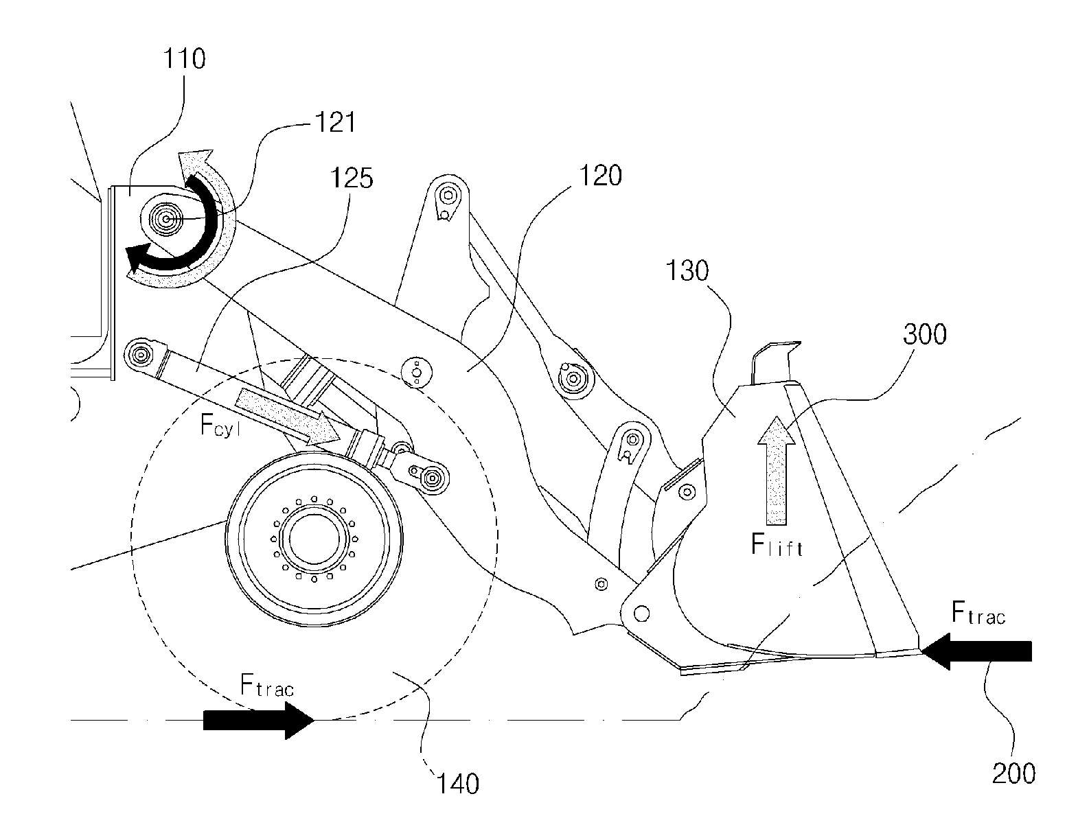
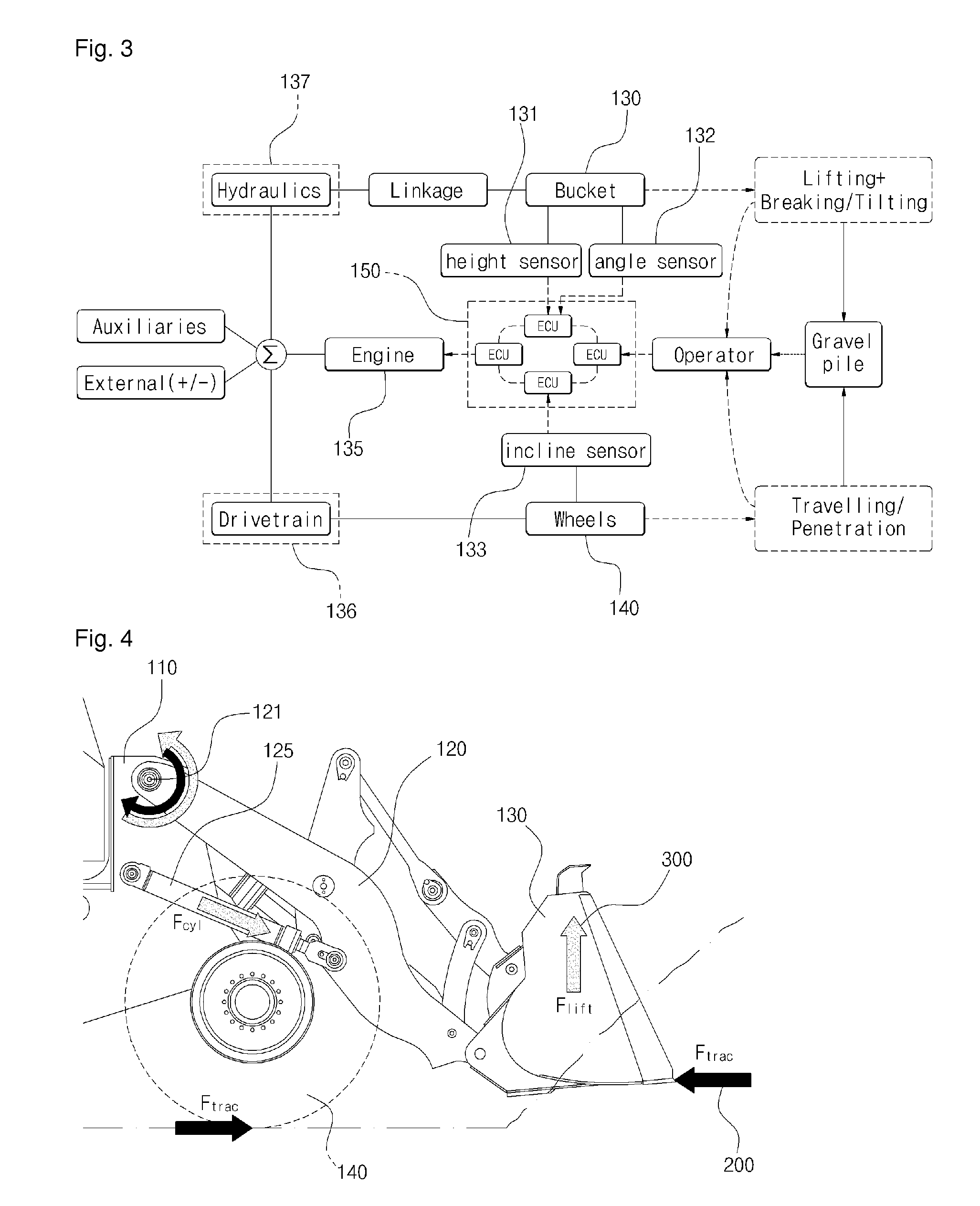
[0047]The invention relates to a method, an electronic control unit, a vehicle control system, and a working machine for controlling a working machine having a bucket as a work implement by which a lifting force can be exerted on an object such as a gravel pile, and at least one ground engaging element by which a traction force can be exerted on the same object, wherein the lifting force is an upward-directed lifting force experienced by the object. The power source of the working machine will be exemplified in the following by an internal combustion engine.

[0048]The electronic control unit, the vehicle control system, and the working machine are adap...


PUM


Abstract

A method for controlling a working machine provided with a bucket as a work implement by which a lifting force can be exerted on an object such as a gravel pile, and at least one ground engaging element by which a traction force can be exerted on the same object is provided. A state input indicative of a current bucket state is received, the bucket height being a parameter of the current bucket state, determining a lifting force eliminating speed of the power source (“LFES”) at the current bucket state, the LFES being the speed at and above which no lifting force could be achieved considering a reaction force acting on the bucket caused by the traction force, and the speed of the power source is controlled not to reach the LFES in order that at least some lifting force could be achieved.

Description

BACKGROUND AND SUMMARY[0001]The present invention relates to a method, an electronic control unit, a vehicle control system, and a working machine for controlling a working machine having a bucket as a work implement. The term ‘power source’, which is described in the following text, is exemplified by an internal combustion engines such as a diesel engine. This should be regarded as a non-limiting example of such a power source.[0002]Such a working machine as a wheel loader or a skid-steer loader is provided with a bucket as a work implement and at least one ground-engaging element such as wheels. The engine in the working machine is used for powering both the movement of the bucket via a hydraulic system and the movement of the machine via a traction system of the machine. Consequently, the operator is constantly challenged to balance the power given to the hydraulic system and the traction system by controlling the hydraulic levers (ex. lift and tilt levers of a wheel loader) and ...

Claims


Application Information

Patent Timeline
Patent Type & Authority Patents(United States)
IPC IPC(8): G06F7/70E02F3/43E02F9/22E02F9/20
CPCE02F3/435E02F3/431E02F9/2029E02F9/2079E02F9/2246
Inventor FILLA, RENOSKOGH, LENNART
Owner VOLVO CONSTR EQUIP AB
Why Eureka
Try Eureka