Side emitting glass element

a side-emitting glass and element technology, applied in the direction of optical light guides, semiconductor devices for light sources, weight reduction, etc., can solve the problems of difficult to produce corresponding preforms, inefficient coupling of light in this case, and complicated use of core geometries

Active Publication Date: 2016-05-03
SCHOTT AG
View PDF13 Cites 8 Cited by
  • Summary
  • Abstract
  • Description
  • Claims
  • Application Information

AI Technical Summary

Benefits of technology

[0017]The absence of a cladding of the individual light guiding elements and the presence of the phase boundary distinguish the glass element according to the invention from side emitting stepped-index fibres in accordance with the prior art. According to the solution according to the invention, the cladding around the individual light guiding elements would impede the guided light from passing through and would reduce the efficiency of the side emission, if not even make it impossible.
[0047]In automotive engineering, in particular, the headlights are increasingly also being used to produce a level of distinctiveness for recognition of the manufacturer by means of special lighting devices. Therefore, some automobile headlights have sidelight rings which surround the dipped beam and appear as a largely homogeneously luminous ring when the light is switched on. Other manufacturers use for example a strip of LEDs in their headlights. The side emitting glass element according to the invention can likewise be used in headlights, in particular in headlights of automobiles, or especially other daytime running light embodiments of automobiles. The glass element according to the invention makes it possible to produce any desired, preferably homogeneously luminous structures in headlights. For various reasons, LEDs are also increasingly finding applications in automobile headlights. Compared with LEDs arranged in strips, this use of the glass element according to the invention has the advantage that a small number of LEDs suffice to produce the illumination. Furthermore, compared with a strip of LEDs, no individual points of light are visible, which may also be preferred for design reasons. Moreover, one or a plurality of LEDs can be coupled into the end face of the glass element according to the invention. It is thus possible to obtain the function as a position light within headlights, which in return include for example the applications as sidelight and / or as daytime running light. By virtue of the fact that the glass element according to the invention is hot-formable, virtually any desired shapes and thus luminous contours can be produced efficiently and with little production outlay.

Problems solved by technology

The production of side emitting fibres by means of such core geometries is beset by the problem, however, that the coupling-out of the light is very inefficient in this case.
Furthermore, it is very complicated to use the core geometries disclosed in JP 9258028 A2 for fibres composed of glass, because it is very difficult to produce corresponding preforms such as are required for fibre drawing.
In this case, it proves to be difficult to produce relatively long fibres having uniformly side emitting properties since the light guiding in the core is attenuated by the admixed particles in the core by absorption since there are no particles which effect total scattering, but rather only those which only almost scatter the entire impinging light.
This means that the coupling-out effect can also be scaled only with very great difficulty, which makes reproducible results complicated to almost impossible.
However, experiments have revealed that if rigid light guides are produced with this solution, they usually have thousands of laterally emitting individual fibres which are mutually superimposed on one another and thus reduce the efficiency of the lateral emission and only a side emission profile extending radially along the fibre axis can be achieved.
Rigid fibres that emit laterally into specific defined solid angles therefore cannot be produced or can at most be produced in an unfavourable manner.
Moreover, a disadvantageous colour bleed effect can be observed, which occurs when white light is radiated into such rigid fibres.
This solution has the disadvantage that the coated glass rod can no longer be subjected to hot processing, that is to say that said rod can no longer be brought to a different form after coating.
Moreover, the layer is sensitive.
Alternatively, the glass rod may be coated after it has been subjected to hot forming, but this places higher demands on the coating technology and thus increases the production outlay in an unacceptable manner for many applications.
Without the phase boundary, the light guiding effect would decrease and working light guides with side-emitting properties in nameable lengths would be hard to achieve.
Moreover, as a result of the form-fit connection, there are no interstices between the light guiding elements into which contaminants could penetrate into the glass element and / or which can lead to undesirable optical effects.
A refractive index n3 deviating significantly from n1 would lead to a reduction of the efficiency of the side emission.
Said lamps have a limited lifetime, for which reason, in such a series, the incandescent lamps that have failed have to be replaced again and again in the course of operation of the airport.
The problem with the use of LEDs is that of being able to realize a sufficiently homogeneously illuminated luminous area therewith.

Method used


Image

  • Side emitting glass element
  • Side emitting glass element
  • Side emitting glass element

Examples


Embodiment Construction

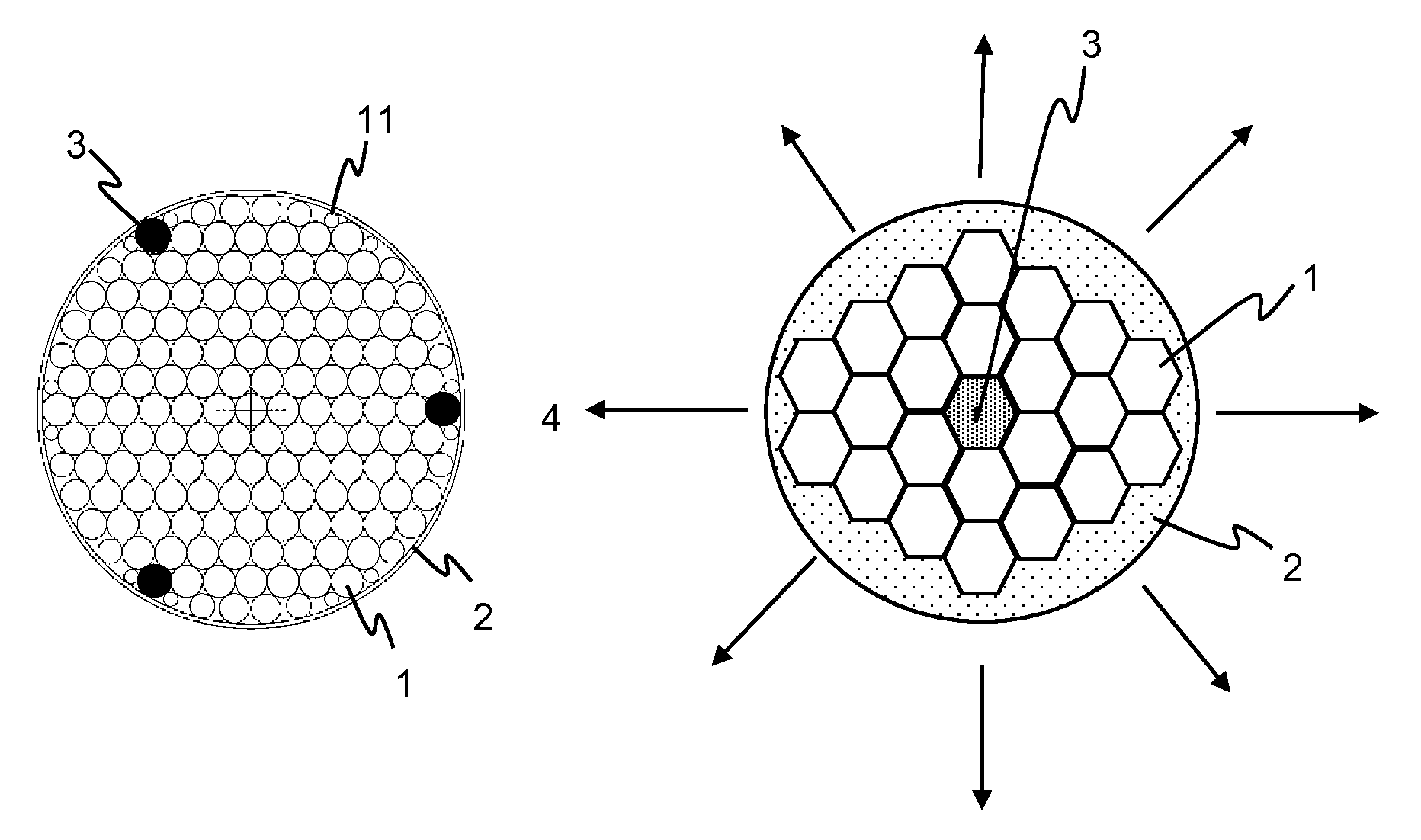
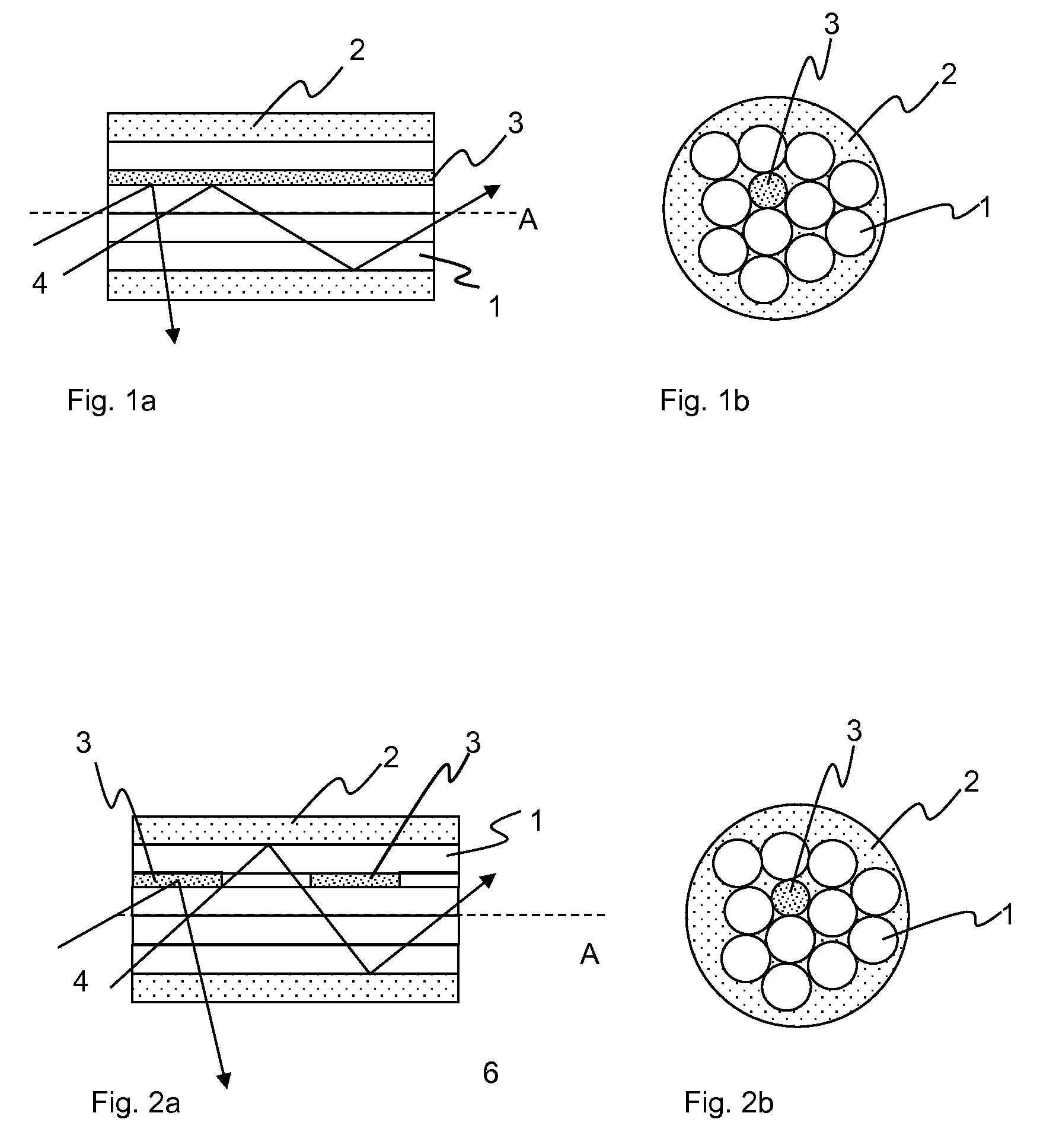
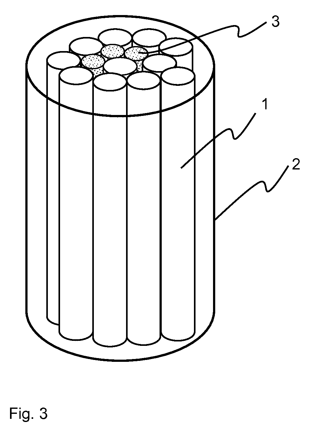
[0071]FIG. 1a schematically shows the longitudinal section along the longitudinal axis A of a side emitting glass element according to the invention. This glass element comprises a scattering element (3) composed of a glass, in which scattering particles produced or incorporated by segregation and / or phase separation are present as scattering centres and which is situated between light guiding elements (1) composed of glass having the refractive index n1. There is a phase boundary between the individual light guiding elements (1) through which a portion of the guided light can pass through and reach the scattering element (3). The cladding (2) composed of glass having the refractive index n2 encloses the glass element along its longitudinal axis (A). Light coupled into the glass element can pass through the phase boundary of the individual light guiding elements (1) and thus from one light guiding element (1) into others and thus reach the scattering element (3). It is coupled out f...


PUM

PropertyMeasurementUnit
diameteraaaaaaaaaa
diameteraaaaaaaaaa
diameteraaaaaaaaaa

Abstract

Side emitting glass elements are provided that include a plurality of light guiding elements, which are inseparably connected to one another at their outer circumferential surfaces, and at least one scattering element. The scattering element is inseparably connected to the outer circumferential surface of at least one light guiding element. The light guiding elements have at least one glass with a refractive index n1, wherein the individual light guiding elements are not enclosed by a cladding. A phase boundary is present between the light guiding elements through which the guided light can pass and to reach the scattering element.

Description

CROSS REFERENCE TO RELATED APPLICATIONS[0001]This application claims benefit under 35 U.S.C. §119(a) of German Patent Application No. 10 2012 208 810.5, filed May 25, 2012, the entire contents of which are incorporated herein by reference.BACKGROUND OF THE INVENTION[0002]1. Field of the Invention[0003]The invention relates to a side emitting glass element which laterally emits portions of the light guided in it, a method for producing said glass element, and the use thereof. Such side emitting glass elements are required for example for lighting applications, be it decorative lighting, signal lighting or the illumination of spaces.[0004]2. Description of Related Art[0005]The light guiding effect of light guided in glass elements is based on the principle of total reflection of the guided light at a medium which surrounds the glass element and which has a lower refractive index. Total reflection occurs when the surrounding medium has a lower refractive index than the glass element gu...

Claims


Application Information

Patent Timeline
Patent Type & Authority Patents(United States)
IPC IPC(8): G02B6/00B60Q1/00B60Q3/00B60Q3/02B64D11/00C03B23/047C03B23/207C03B37/012F21K99/00F21S8/10F21V8/00G02B6/04
CPCC03B37/01205C03B37/01211C03B37/0124C03B23/047C03B23/207B60Q1/0041B64D2203/00G02B6/04B64D2011/0038B64D11/00F21K9/20F21K9/61F21Y2115/10B60Q3/64B60Q3/41F21S43/14F21S43/237F21S43/245F21S43/249G02B6/001Y02T50/40C03B37/01222
Inventor RUSSERT, HUBERTUS
Owner SCHOTT AG
Why Eureka
Try Eureka