
Electro-mechanical drug delivery device

a technology of electronic mechanical and drug delivery, which is applied in the direction of automatic syringes, infusion syringes, transportation and packaging, etc., can solve the problems of not being varied by healthcare professionals or users, quantity and/or proportion of each active agent, and mixed formulations containing two or more active agents may not be varied, so as to prevent the potential risk of double dosing and facilitate titration

Active Publication Date: 2016-05-17
SANOFI AVENTIS DEUT GMBH
View PDF9 Cites 11 Cited by
  • Summary
  • Abstract
  • Description
  • Claims
  • Application Information

AI Technical Summary

Benefits of technology

The drug delivery device described in this patent prevented the administration of a drug when the separable housing is decoupled from the main body, which could potentially electrocute the user. The device also prevents the creation of an electrical connection between the conduction element and the external device, reducing the risk of user errors and increasing patient safety. Additionally, the device delivers both medications in one injection step, reducing user steps and improving compliance with the prescribed therapy.

Problems solved by technology

There are a number of potential problems when delivering two active medicaments or “agents” simultaneously.
A further problem that may often arise is that the quantities and / or proportions of each active agent making up the combination therapy may need to be varied for each user or at different stages of their therapy.
Because of such a potential problem, certain pre-mixed formulations comprising two or more active agents may not be suitable as these pre-mixed formulations would have a fixed ratio of the active components, which could not be varied by the healthcare professional or user.
Additional problems can arise where a multi-drug compound therapy is required, because many users cannot cope with having to use more than one drug delivery system or make the necessary accurate calculation of the required dose combination.
Other problems arise where a drug delivery system requires the user to physically manipulate the drug delivery device or a component of the drug delivery device (e.g., a dose dialing button) so as to set and / or inject a dose.

Method used


Image

  • Electro-mechanical drug delivery device
  • Electro-mechanical drug delivery device
  • Electro-mechanical drug delivery device

Examples


Embodiment Construction

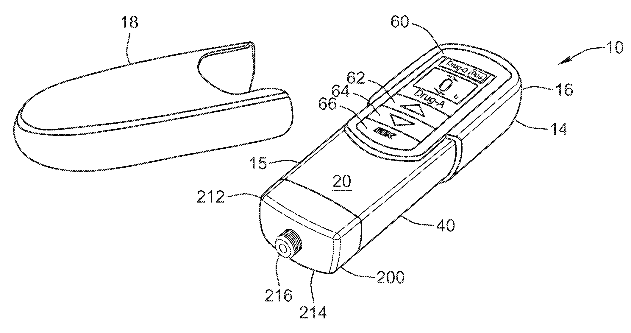
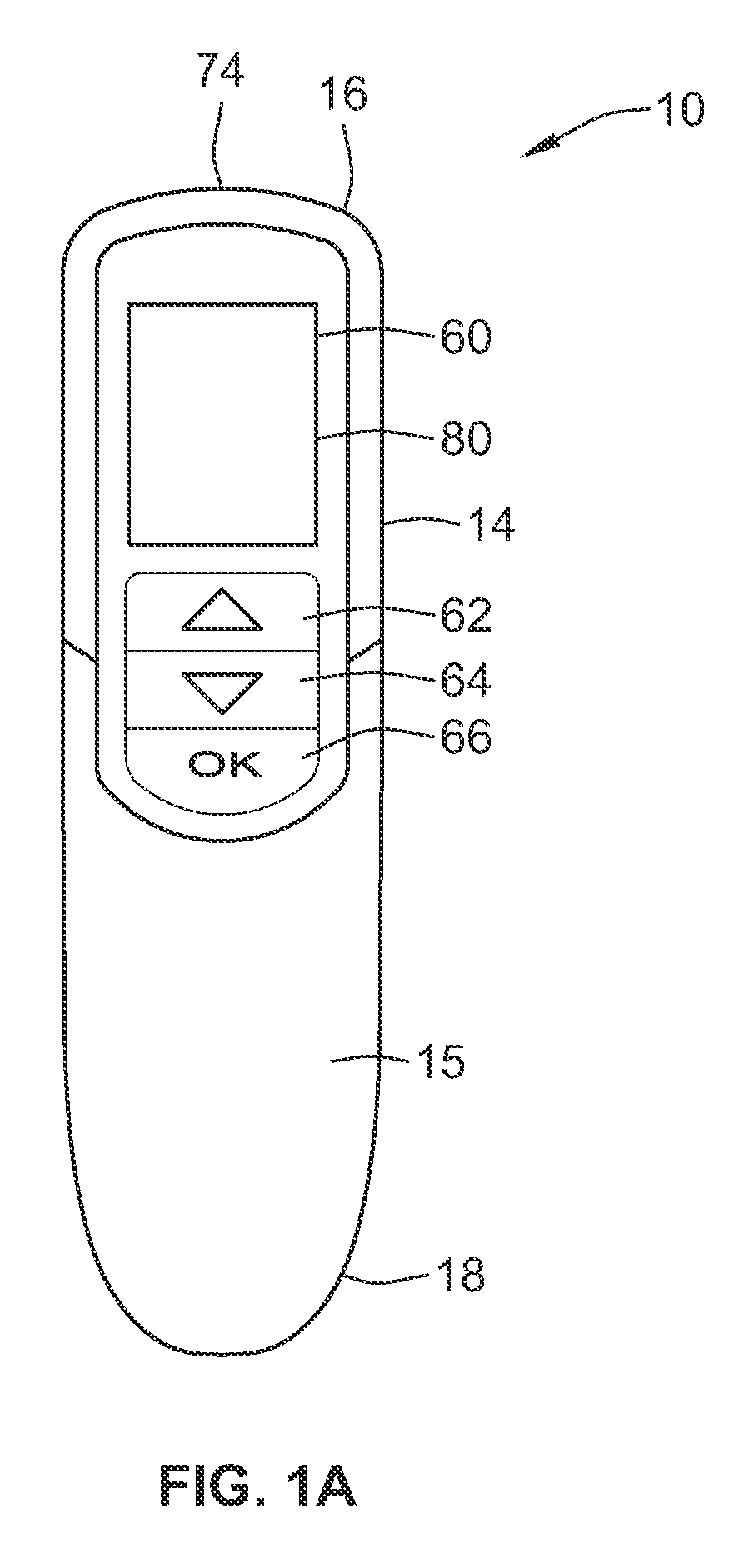
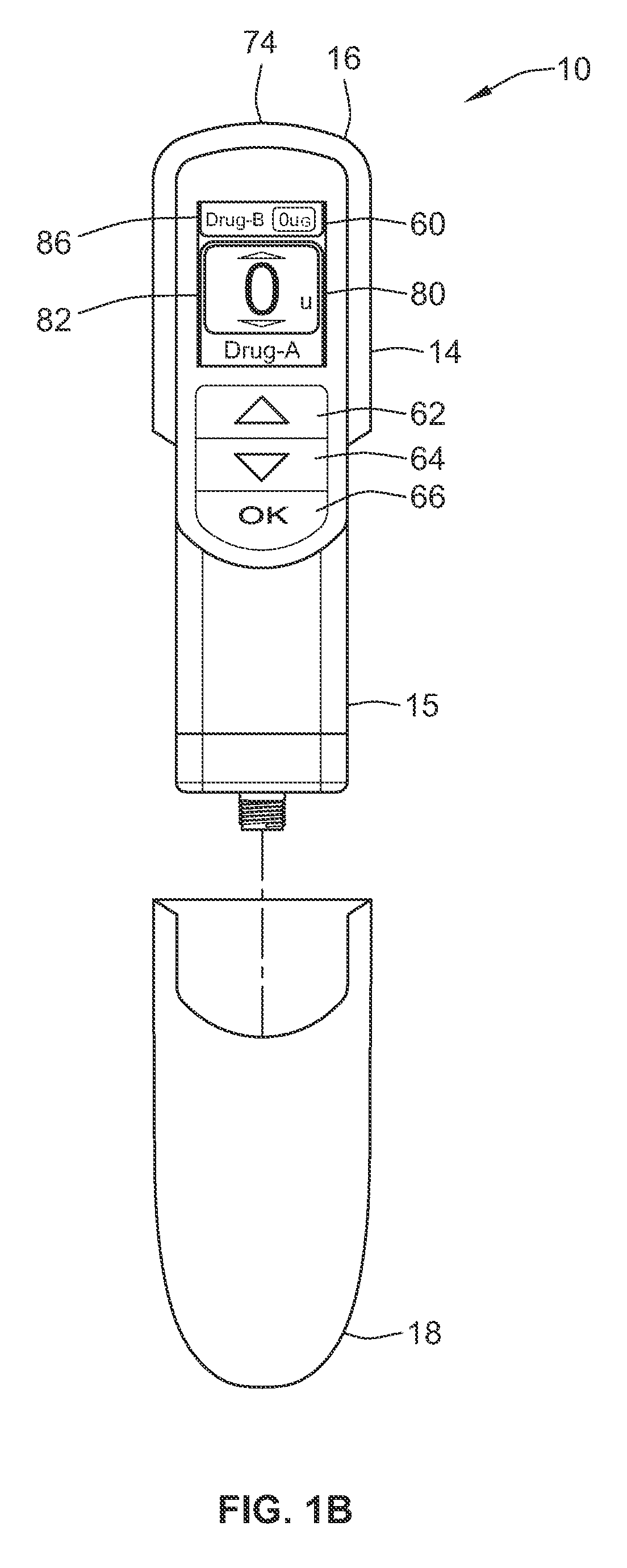
[0153]FIGS. 1a and 1b illustrate plan views of a programmable drug delivery device 10 in accordance with one aspect of the present disclosure. FIG. 1a illustrates the device 10 when an end cap 18 is on the device 10. In FIG. 1b, the device 10 is illustrated in a ready mode in that the end cap 18 is off and the device 10 has been turned on so that the digital display 80 is illuminated. When the device is activated with the cap on only cartridge contents, battery status and last dose information will be available for display. When the cover is removed the dose setting screen will be available. FIG. 2 illustrates a perspective view of the delivery device 10 illustrated in FIGS. 1a and 1b with the end cap 18 of the device 10 removed. In FIG. 2, the device is turned on so that the digital display is illuminated. FIG. 3 illustrates a perspective view of a cartridge holder and the back side of the delivery device illustrated in FIGS. 1a and 1b. FIG. 4 illustrates a perspective view of a pr...


PUM


Abstract

An electro-mechanical drug delivery device comprises a main body having a distal end and a proximal end. The distal end is configured to attach to a dispense interface. A separable housing that can prevent an administration of a drug by the drug delivery device, the housing configured to cover at least a portion of the distal end of the main body when the separable housing is coupled to the main body of the drug delivery device. A conduction element is provided by the main body and configured for establishing an electrical connection with an electrical connector. Establishment of the electrical connection is prevented when the housing does not cover at least a portion of the distal end of the main body. The electrical connection may be established when the housing covers at least a portion of the distal end of the main body of the drug delivery device.

Description

CROSS REFERENCE TO RELATED APPLICATIONS[0001]The present application is a U.S. National Phase Application pursuant to 35 U.S.C. §371 of International Application No. PCT / EP2011 / 054649 filed Mar. 25, 2011, which claims priority to U.S. Provisional Patent Application No. 61 / 318,118 filed Mar. 26, 2010 and European Patent Application No. 10168936.2 filed Jul. 8, 2010. The entire disclosure contents of these applications are herewith incorporated by reference into the present application.FIELD OF THE INVENTION[0002]According to one aspect, the present disclosure relates to a drug delivery device configured for establishing an electrical connection to an electrical connector. As an example, the drug delivery device may be an electro-mechanical device. The electrical connector may be an external connector.[0003]According to further aspects, the present disclosure relates to medical devices and methods of delivering at least two drug agents from separate reservoirs using a device having a ...

Claims


Application Information

Patent Timeline
IPC IPC(8): A61M5/20A61M5/00A61M5/19A61M5/24A61M5/31A61M5/315H02J7/00A61M39/10A61M5/34
CPCA61M5/20A61M5/002A61M5/19A61M5/24A61M5/2448A61M5/3146A61M5/31546A61M5/345A61M2005/2496A61M2005/3104A61M2005/3125A61M2005/3126A61M2005/3128A61M2005/31588A61M2039/1083A61M2039/1088A61M2205/3584A61M2205/50A61M2205/505A61M2205/52A61M2205/6072A61M2205/8206A61M2205/8212A61M2205/8256A61M2209/086H02J7/0047H02J7/0048H02J2310/23
Inventor WIMPENNY, STEVENO'HARE, AIDAN MICHAELYATES, BARRYDAY, SHANE ALISTAIR
Owner SANOFI AVENTIS DEUT GMBH
Learn More