Method, system, and control apparatus for setting over-current protection point of electronic device

a technology of electronic devices and protection points, applied in the field of electronic devices, can solve the problems of slow operation speed, serious blockage of productivity promotion, and even damage to electronic devices, and achieve the effect of improving stability or consistency of setting over-current protection points and saving labor costs

Inactive Publication Date: 2016-05-17
DELTA ELECTRONICS (SHANGHAI) CO LTD
View PDF15 Cites 0 Cited by
  • Summary
  • Abstract
  • Description
  • Claims
  • Application Information

AI Technical Summary

Benefits of technology

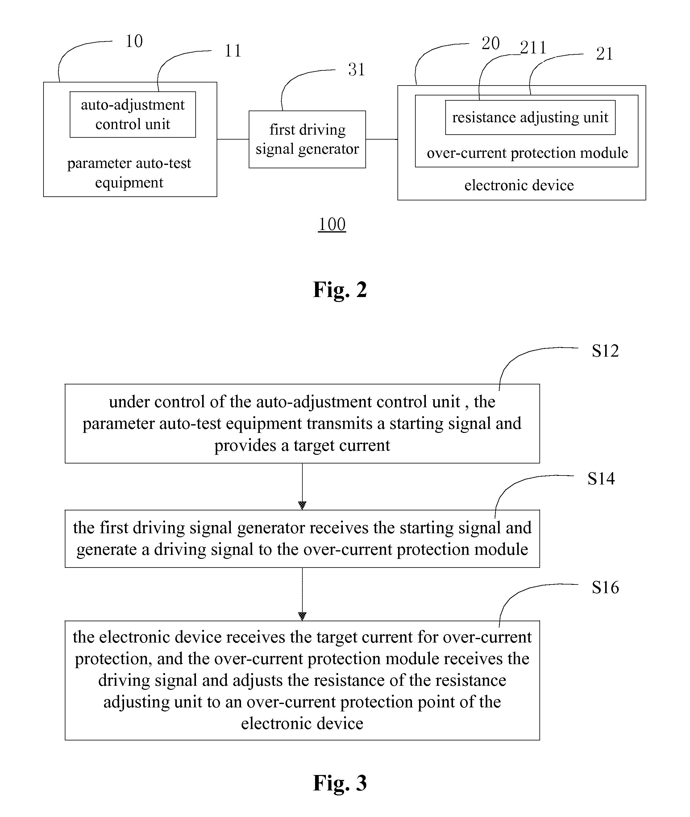
[0033]The present invention attain an auto-adjustment on the resistance of the resistor in the over-current protection module by means of the driving signal generator, the parameter auto-test equipment provided with the auto control adjust unit and the driving signal outputted by the driving signal generator, so that the auto-setting of the over-current protection point of the electronic device is attained. Therefore, technical contents which are disclosed by the invention can attain fully automatic operation on the over-current protection point of the electronic device, save labor cost, and improve stability or consistency of setting the over-current protection point.

Problems solved by technology

Many electronic devices have a rated current for operation, if an operating current of the electronic device at present exceeds the rated current, it would cause the electronic device to stop operation and even to be damaged.
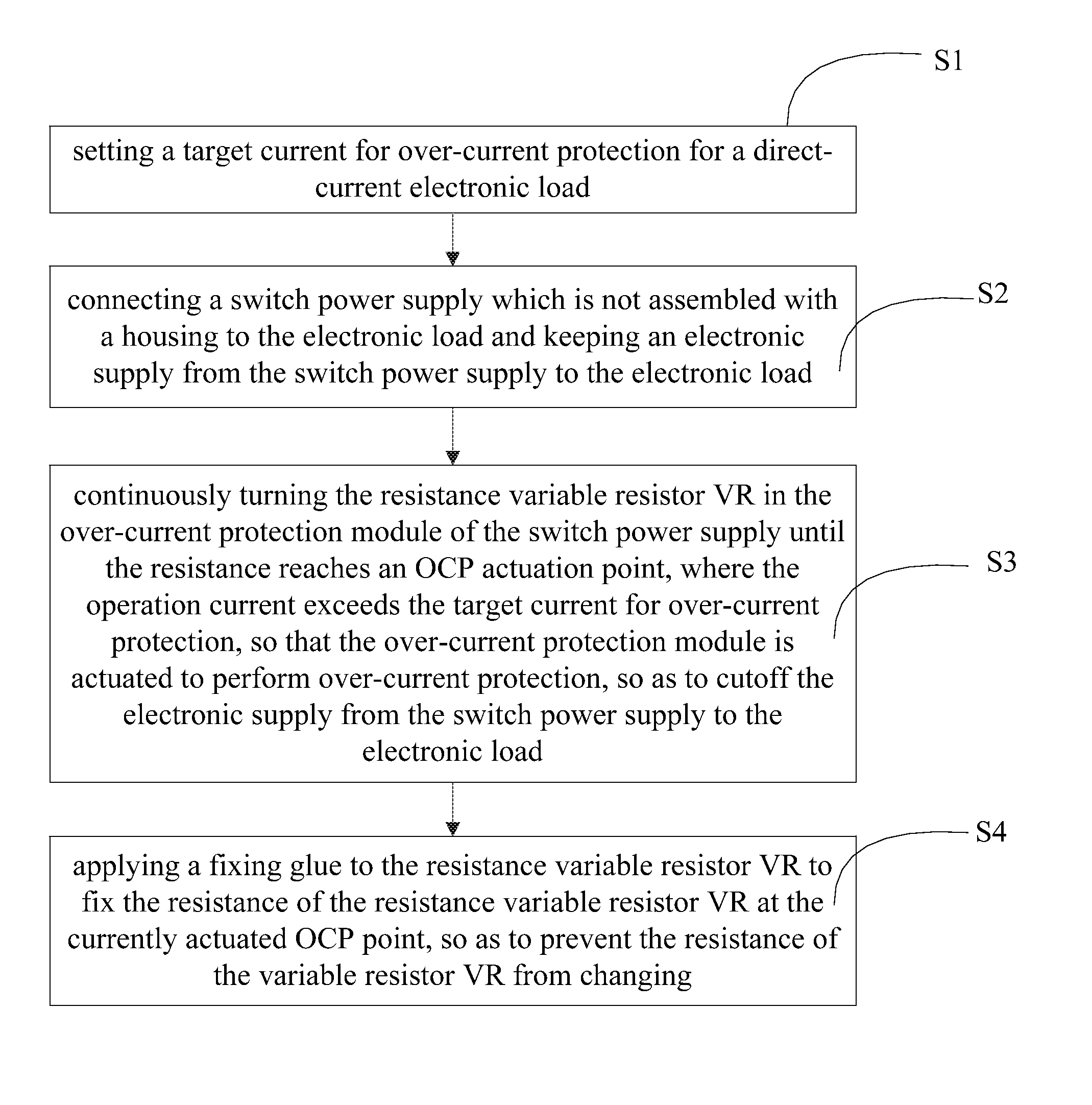
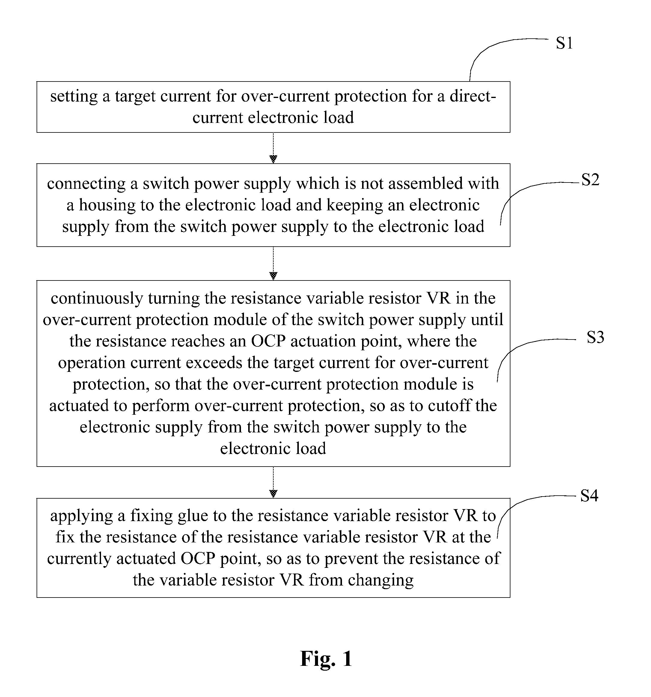
However, each of the above steps is performed manually, which slows operating speed and seriously blocks promotion of productivity.
At the same time, it is difficult for manual operation to assure higher correctness, because it is easily to manually change the resistance of the variable resistor VR.
Moreover, since the fixing glue may shrink during cooling and may expand during heating, it is easily to have the secured resistance of the variable resistor VR displaced and offset from the OCP point which has been set, seriously affecting the quality of the electronic device.

Method used


Image

  • Method, system, and control apparatus for setting over-current protection point of electronic device
  • Method, system, and control apparatus for setting over-current protection point of electronic device
  • Method, system, and control apparatus for setting over-current protection point of electronic device

Examples


application example

[0056]The invention which is disclosed above will be further described hereinafter by a specific application example of the method and the system for the over-current protection point of the electronic device disclosed by the above embodiments.

[0057]In this specific application example, the electronic device is a switch power supply, such as a switch power supply in a computer mainframe. During the manufacture of the switch power supply, in addition to other testing items that are conventionally required to be tested, the over-current protection point is further required to be set and tested so as to attain a self-protection function of the product itself.

[0058]Referring to FIG. 7, a specific block diagram illustrating the whole setting system of the specific application example, the whole setting system comprises a control apparatus for setting the over-current protection point of the electronic device. The setting system comprises a parameter auto-test equipment 10. The auto-testi...


PUM


Abstract

A method, a system, and a control apparatus for setting an over-current protection point of an electronic device are provided. The method comprises: step 1, the parameter auto-test equipment transmitting a starting signal and outputting a target current for over-current protection based on the auto-adjustment control unit; step 2, the first driving signal generator receiving the starting signal and transmitting a driving signal to the over-current protection module; and step 3, the electronic device receiving the target current for over-current protection, and the over-current protection module receiving the driving signal and adjusting a resistance of the resistance adjusting unit to the over-current protection point of the electronic device. The invention attains fully automatic operation on the over-current protection point of the electronic device, improves stability and consistency of setting the over-current protection point, and saves labor cost at the same time.

Description

CROSS-REFERENCE TO RELATED APPLICATIONS[0001]This non-provisional application claims priority under 35 U.S.C. §119(a) on Patent Application No. 201210220045.0 filed in P.R. China on Jun. 29, 2012, the entire contents of which are hereby incorporated by reference.[0002]Some references, if any, which may include patents, patent applications and various publications, may be cited and discussed in the description of this invention. The citation and / or discussion of such references, if any, is provided merely to clarify the description of the present invention and is not an admission that any such reference is “prior art” to the present invention described herein. All references listed, cited and / or discussed in this specification are incorporated herein by reference in their entireties and to the same extent as if each reference was individually incorporated by reference.FIELD OF THE PRESENT APPLICATION[0003]The present application relates to a manufacturing field of an electronic devic...

Claims


Application Information

Patent Timeline
Patent Type & Authority Patents(United States)
IPC IPC(8): G01R35/00H02H3/00H02H3/08
CPCG01R35/007H02H3/006H02H3/08
Inventor XIE, LIUQUNHU, XIANGRONG
Owner DELTA ELECTRONICS (SHANGHAI) CO LTD
Why Eureka
Try Eureka