
Cartridge holder and drug delivery device

a cartridge and cartridge technology, applied in the direction of intravenous devices, infusion needles, syringes, etc., can solve the problems of axial displacement of the cartridge and/or its septum at the expense of dosing accuracy, and achieve the effects of improving dosage accuracy, stable and robust design of the drug delivery device, and low cos

Active Publication Date: 2016-05-24
SANOFI AVENTIS DEUT GMBH
View PDF3 Cites 0 Cited by
  • Summary
  • Abstract
  • Description
  • Claims
  • Application Information

AI Technical Summary

Benefits of technology

[0013]It is therefore an object of the present invention, to provide an improved cartridge holder for a drug delivery device, which counteracts generation of droplets after termination of a dose dispensing procedure. As a further aim, the invention focuses on improvements with respect to dosage accuracy. Furthermore, the invention aims to provide an inexpensive as well as stable and robust design of a drug delivery device.SUMMARY OF THE INVENTION
[0019]By way of the retaining means, the cartridge can be axially fixed with respect to the cartridge holder and / or with respect to the housing of the drug delivery device. In this way, axial displacement of the cartridge inside the cartridge holder and / or inside the housing of the drug delivery device can be effectively counteracted or even entirely prevented. The retaining means are at least adapted to fix the cartridge in proximal direction with respect to the cartridge holder's proximal portion. The retaining means may even be adapted to fix the cartridge in distal direction with respect to the cartridge holder.
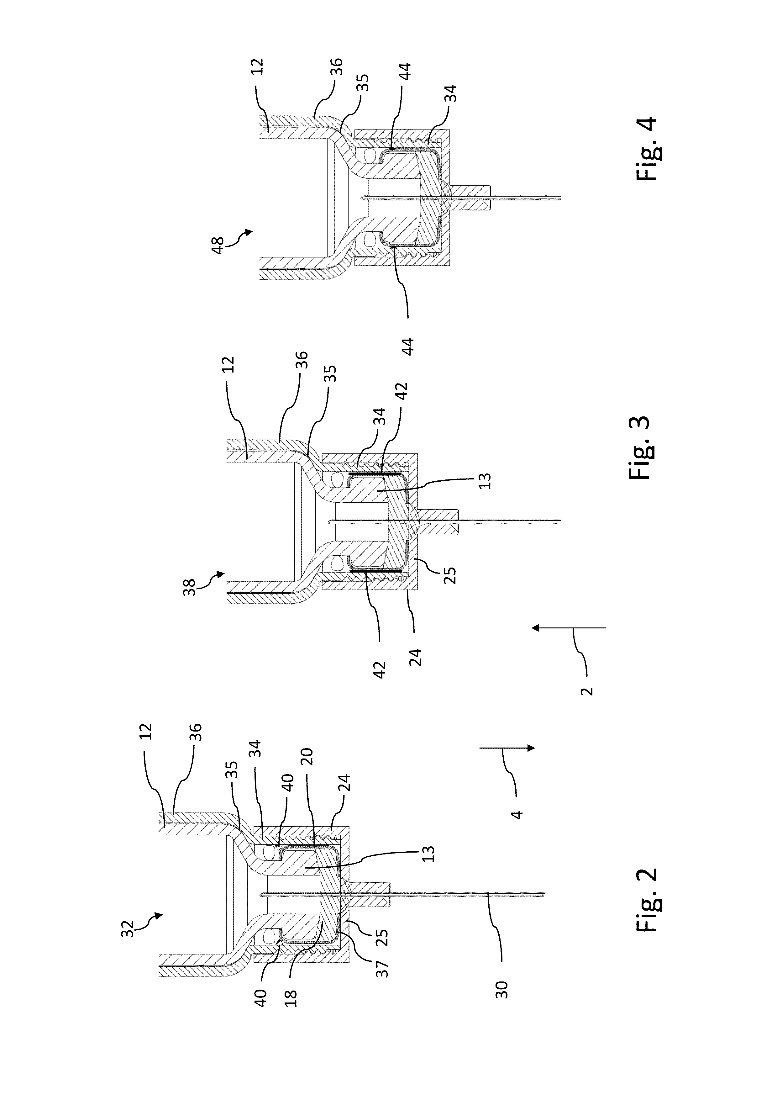
[0029]Since the distal portion of the cartridge comprises an indentation, the retaining means, for instance in form of radially inwardly protruding struts, are axially arranged in the region of said indentations. In this way, even a positive mutual axial interlocking of the indentation and radially inwardly protruding struts can be achieved.
[0031]According to another embodiment, the radial distance between radially inwardly protruding retaining means, in particular of radially inwardly protruding struts and / or axially extending ribs is smaller than the radial dimensions of the distal neck portion of the cartridge. In this way, insertion of the cartridge into the cartridge holder yields to a deformation of the respective struts and / or ribs, such that a clamping effect between cartridge holder and cartridge can be attained in such a way that the cartridge is substantially fixed to cartridge holder.
[0034]According to a further preferred embodiment, the distal portion of the cartridge holder comprises at least one axially extending slit, that divides the distal portion into at least two radially inwardly deformable distal segments. The axial slit also intersects the outside thread of the distal portion. Moreover, the distal segments of the cartridge holder might be subject to a radially outwardly directed pre-tension, which may facilitate insertion of the cartridge into the distal portion of the cartridge holder. By subsequently screwing the cupped piercing assembly on the distal portion of the cartridge holder, the distal segments of the cartridge holder become subject to a radially inwardly directed deformation, by way of which a mutual clamping of cartridge holder and cartridge can be established and / or further enhanced.
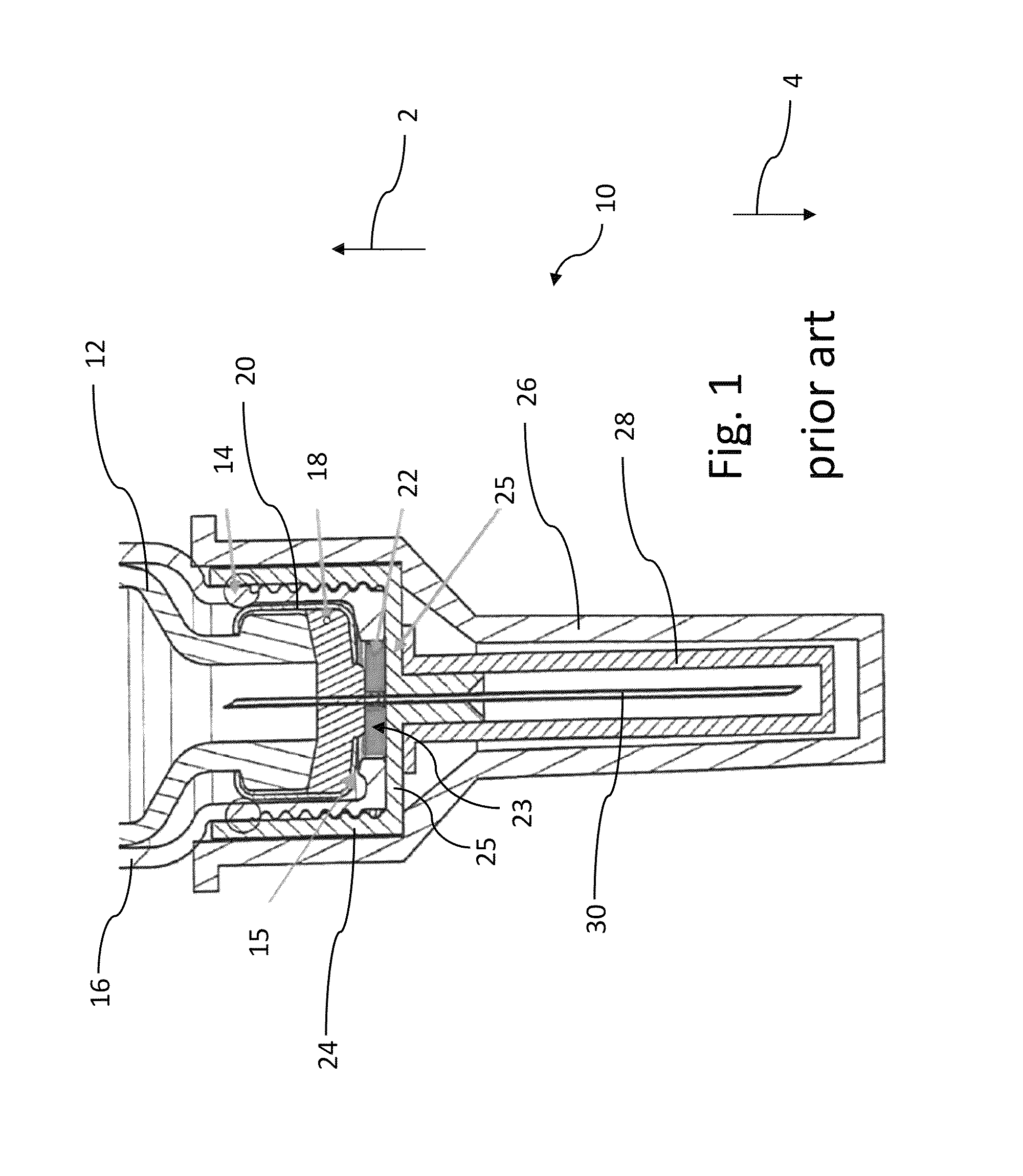
[0035]In a further preferred embodiment, the distal portion of the cartridge holder is opened towards its distal end. In contrast to prior art solutions, such as illustrated in FIG. 1, the distal portion of the cartridge holder according to the present invention does not comprise such radially inwardly directed flange portions. In this way, the distal end face of the cupped piercing assembly provides a distal end stop for the cartridge almost across the entire inner surface of its bottom portion, when assembled with the cartridge holder. This is of particular benefit, since the distal end face of the cartridge itself buts against a distal end stop of the needle mount or piercing assembly, respectively. By having such an abutment configuration, distally directed axial displacement of the septum can be effectively prevented and droplet generation is counteracted.

Problems solved by technology

Generally, any axial displacement of the cartridge and / or its septum is finally at the expense of dosing accuracy.

Method used


Image

  • Cartridge holder and drug delivery device
  • Cartridge holder and drug delivery device
  • Cartridge holder and drug delivery device

Examples


Embodiment Construction

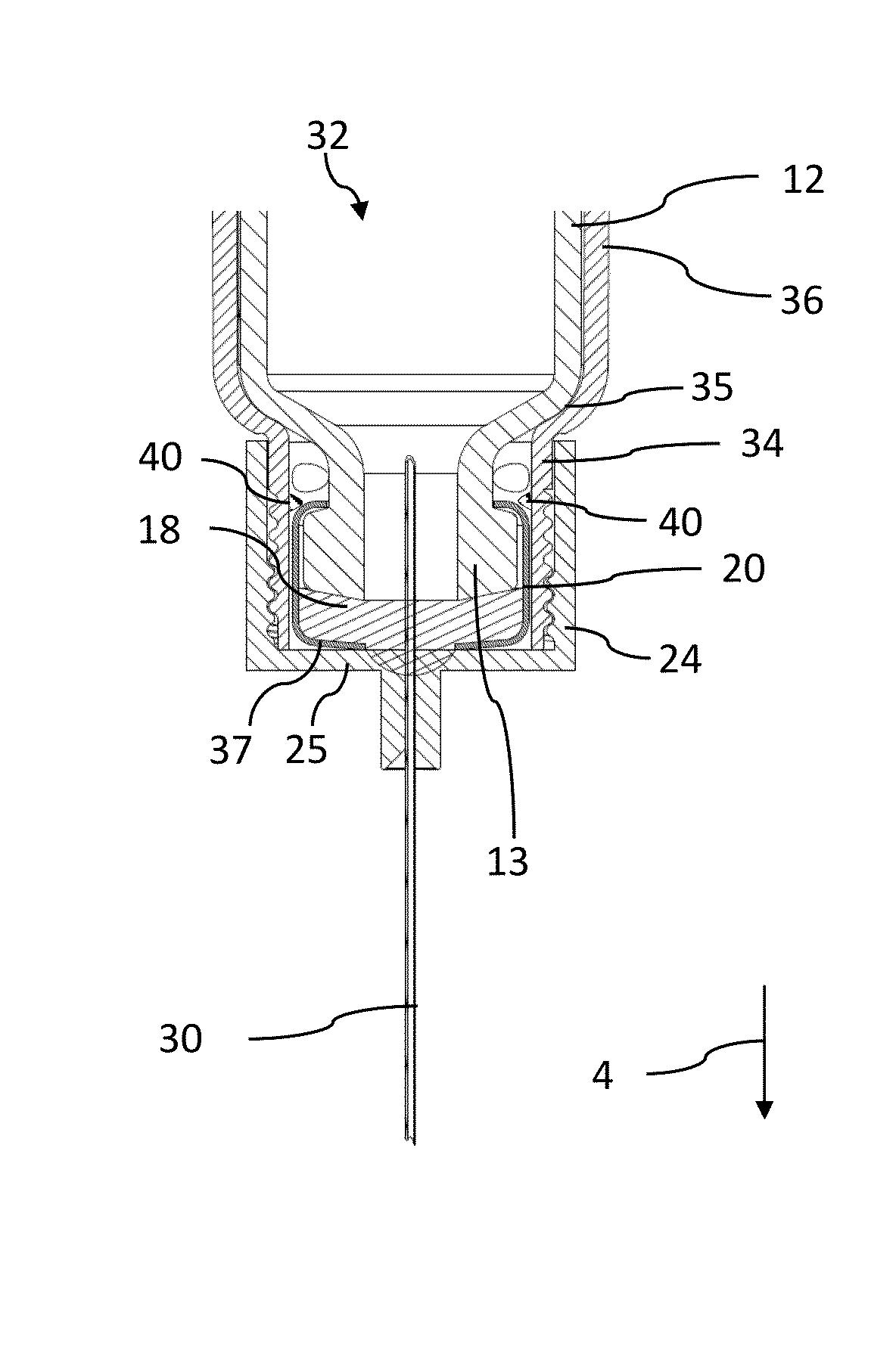
[0105]In contrast to a cartridge holder assembly 10 according to the prior art as illustrated in FIG. 1, the cartridge holders 32, 38, 48 according to the present invention as depicted in FIGS. 2 through 4 do no longer comprise a radially inwardly directed flange portion 15 at their distal end section. Hence, the cartridge holders 32, 38, 48 comprise a distal end having an inner diameter that corresponds to the outer diameter of a stepped down distal neck portion 13 of a cartridge 12 to be inserted and to be received by the respective cartridge holders 32, 38, 48.

[0106]As illustrated throughout FIGS. 1 to 4, the proximal direction is depicted with an upward pointing arrow 2 and the distal direction is indicated by a downward pointing arrow 4.

[0107]As can further be seen from the sketches of FIGS. 2 to 4 a distal portion of the aluminium cap 20 directly buts against the bottom portion 25 of the needle holder 24. Axially and distally directed expansion of the septum 18 is therefore ef...


PUM


Abstract

A cartridge holder for a drug delivery device. The cartridge holder comprises a proximal portion for receiving a cartridge filled with a medicinal fluid to be dispensed by the drug delivery device, and a distal portion comprising a mount for a piercing assembly. The piercing assembly is adapted to provide a fluid-transferring connection with the inner volume of the cartridge by way of a piercing element pointing in distal direction with a pointed free end section. Retaining means adapted to substantially prevent the cartridge from displacing in proximal direction with respect to the proximal portion distal portion.

Description

CROSS REFERENCE TO RELATED APPLICATIONS[0001]The present application is a 35 U.S.C. 371 National Application of PCT / EP2010 / 068595 filed Dec. 1, 2010, which claims priority to European Patent Application No. 09177684.9, filed Dec. 2, 2009, the entire contents of which are incorporated entirely herein by reference.FIELD OF THE INVENTION[0002]The present invention relates to the field of drug delivery devices an in particular to cartridge holders of drug delivery devices such like pen-type injectors, hence to injectors of the kind that provide for administration of medicinal products by way of injection from a multi dose cartridge. Preferably, the present invention relates to such injectors, where a user may set and dispense the dose.BACKGROUND AND PRIOR ART[0003]User operated drug delivery devices are as such known in the prior art. They are typically applicable in circumstances, in which persons without formal medical training, i.e., patients, need to administer an accurate and prede...

Claims


Application Information

Patent Timeline
Patent Type & Authority Patents(United States)
IPC IPC(8): A61M5/24A61M5/34
CPCA61M5/24A61M5/2466A61M5/347
Inventor JUGL, MICHAELTEUCHER, AXELHEMMANN, KERSTINE
Owner SANOFI AVENTIS DEUT GMBH
Learn More