Molding element for a tire mold comprising a porous area

a technology of molding element and porous area, which is applied in the field of molding element, can solve the problems of reducing material density, affecting the quality of molds,

Active Publication Date: 2016-05-24
MICHELIN & CO CIE GEN DES ESTAB MICHELIN
View PDF12 Cites 2 Cited by
  • Summary
  • Abstract
  • Description
  • Claims
  • Application Information

AI Technical Summary

Benefits of technology

[0021]The first porous area allows air to pass between the inside of the mold and the outside of this mold when the latter is closed. Because the overall density of the molding element remains greater than or equal to 98% despite the presence of this first porous area, good removal of air from the mold during the vulcanizing operation is ensured while at the same time maintaining good mechanical strength of the molding element.
[0023]By organizing the first porous area in such a way that it is able to create a predefined pattern on the tire, the overall appearance of the tire is improved.
[0025]The second surface of the molding element will come into contact with another part of the mold. Contact between the molding element and this other part is not generally entirely airtight. By creating a second porous area in the molding element at the interface with the other part of the mold, the removal of air from the mold is improved without the need to make a hole in the other part of the mold. This then makes the mold easier to manufacture.
[0027]The point at which two protrusions intersect on the first surface of the element is particularly critical because a large amount of air can build up at this point as the mold is closed over the green tire. By making the porous area open onto the intersection of two protrusions, it becomes easier to remove air from the mold and the appearance of surface defects on the tread once this tread has been vulcanized is limited.

Problems solved by technology

However, the presence of a high number of pores in the molding element reduces the material density of this element and makes it more fragile to mechanical loading.
Thus, the venting solutions disclosed in documents DE102004028462 and DE102004052766, if applied to the molding element of document WO2010 / 076502, would make the latter element too fragile because of its small thickness.

Method used


Image

  • Molding element for a tire mold comprising a porous area
  • Molding element for a tire mold comprising a porous area
  • Molding element for a tire mold comprising a porous area

Examples


second embodiment

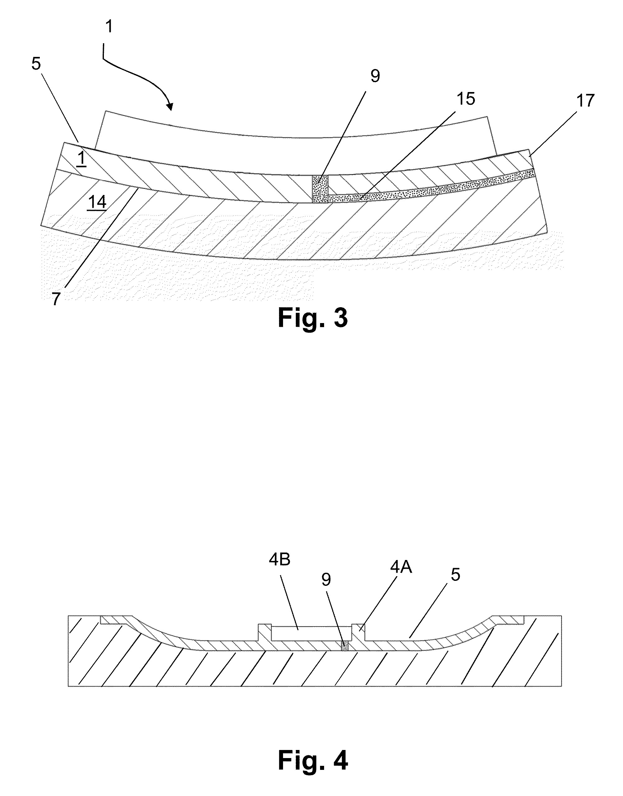
[0041]FIG. 3 is a view in cross section of the molding element 1 of FIG. 1 in a plane perpendicular to the plane of FIG. 2. The molding element 1 is depicted here as being an element attached to another part 14 of the mold. More specifically, in this embodiment, the molding element 1 comprises a second porous area 15. This second porous area 15 here forms part of the second surface 7 of the molding element 1. More particularly, this porous area 15 connects the cavity 9 to a lateral surface 17 of this molding element 1. The lateral surface 17 is the surface of the element 1 that connects the first surface 5 to the second surface 7. In this way, air is removed from the mold via the first porous area 9 and the second porous area 15 and this is done without the need to make a hole in the other part 14 of the mold.

third embodiment

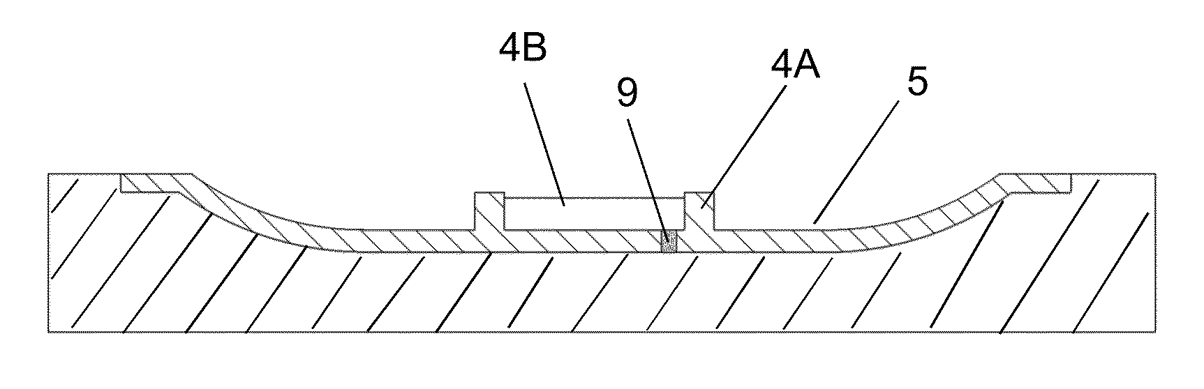
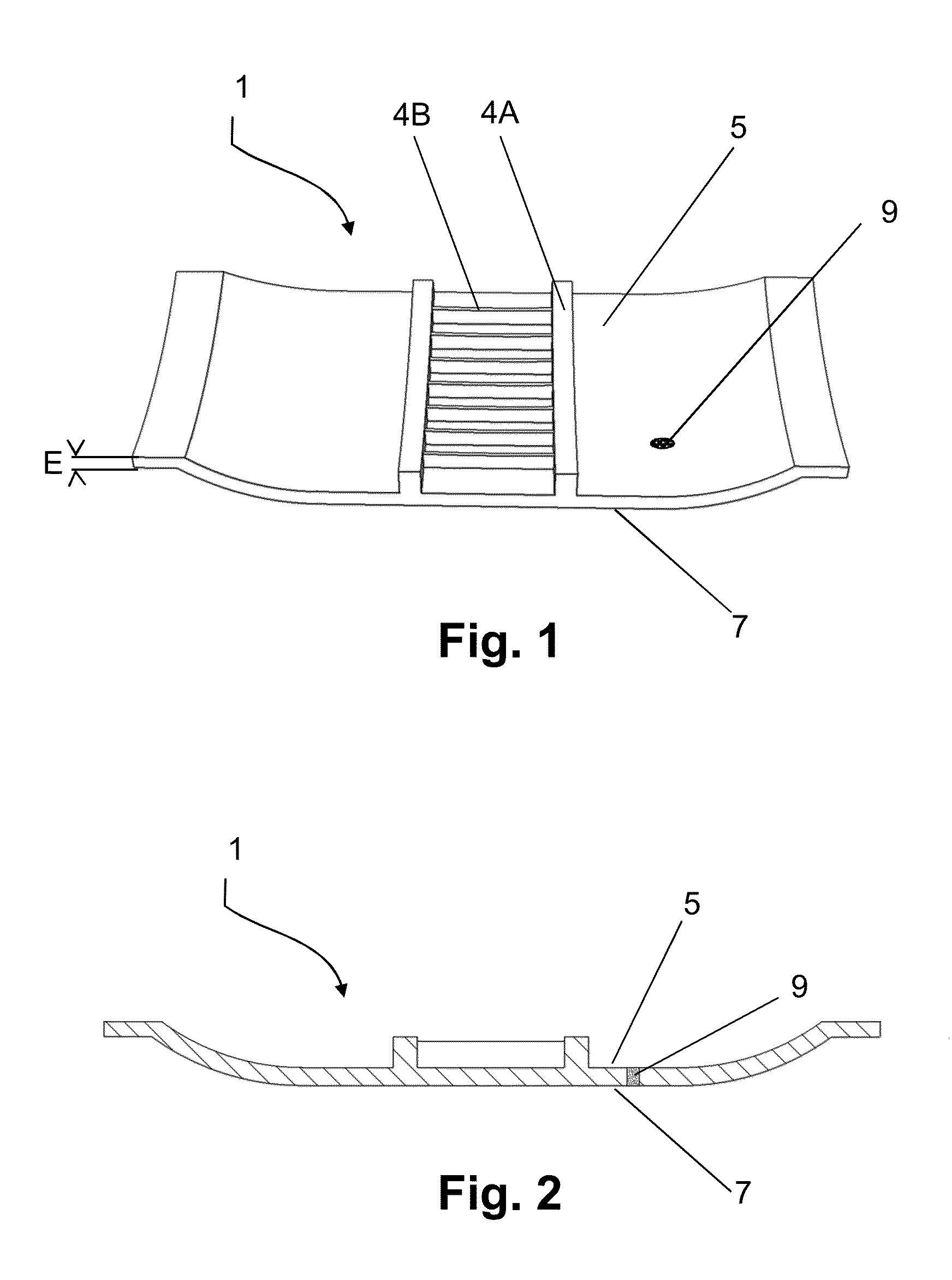
[0042]FIG. 4 depicts a third embodiment in which the first area 9 opens out at the intersection of two protrusions 4A, 4B. The removal of air from the vicinity of the protrusions when the mold is closed over the green tire is thus improved.

[0043]FIG. 5 shows one step in a method of the layer-by-layer manufacture of the molding element of FIG. 1. This method comprises a plurality of steps of depositing layers 19 of metallic particles and of agglomerating all or some of the particles of these layers by fusion using a laser 20. For each of the layers of the molding element, a porous part 21 is created during the step of agglomerating the particles. The porous parts of the various layers are superposed with one another to form a continuous porous zone extending into the thickness of the molding element. These porous parts may be superposed with one another exactly in the thickness of the molding element as is depicted in FIG. 5. As an alternative, there may be an offset between the poro...


PUM

PropertyMeasurementUnit
thicknessaaaaaaaaaa
thicknessaaaaaaaaaa
diameteraaaaaaaaaa

Abstract

A molding element for a tire mold manufactured from a metallic powder fused together layer by layer. The molding element contains a first surface intended to mold all or part of a tread surface of the tire and a second surface opposite to the first surface and intended to be in contact with another part of the mold. The thickness (E) of the molding element is between 1 and 6 millimeters. The molding element overall has a density greater than or equal to 98%. The molding element also contains at least one first porous area extending into the thickness of this molding element, this first porous area having a plurality of pores allowing air to pass between the first surface of the molding element and the second surface thereof.

Description

[0001]This application is a 371 national phase entry of PCT / EP2013 / 070395, filed 1 Oct. 2013, which claims benefit of French Patent Application No. 1259902, filed 17 Oct. 2012, the entire contents of which are incorporated herein by reference for all purposes.BACKGROUND[0002]1. Field[0003]The present disclosure relates to a molding element obtained by sintering and comprising particular venting means. The molding element is intended to be arranged in a tire mold, notably a mold of the segmented type. The invention also relates to a method for producing such a molding element.[0004]2. Description of Related Art[0005]A segmented mold comprises several separate parts which, when brought relatively closer together, delimit a molding space of toroidal overall shape. In particular, a segmented mold comprises two lateral shells for molding the sidewalls of the tire and several peripheral segments situated between the shells for molding the tread of the tire. All of these parts are brought ...

Claims


Application Information

Patent Timeline
Patent Type & Authority Patents(United States)
IPC IPC(8): B29D30/06B22F3/105B29C33/38B29C33/10
CPCB29D30/0606B22F3/1055B29C33/10B29C33/3814B29D2030/0612B29D2030/0614B29D2030/0617B29D30/0629Y02P10/25B22F10/28
Inventor CALVEL, ROMAINBLANCHET, ETIENNE
Owner MICHELIN & CO CIE GEN DES ESTAB MICHELIN
Why Eureka
Try Eureka