

Illuminating optical system and projection display apparatus
a technology of illumination optical system and projection display apparatus, which is applied in the direction of lighting and heating apparatus, picture reproducers using projection devices, instruments, etc., can solve the problems of non-uniform light intensity of illuminating light beam output from rod integrator after passing therethrough, deterioration of quality of illuminating light beam, and inability to achieve uniform light intensity, the effect of suppressing generation of illumination fluctuations
- Summary
- Abstract
- Description
- Claims
- Application Information
AI Technical Summary
Benefits of technology
Problems solved by technology
Method used
Image

Examples
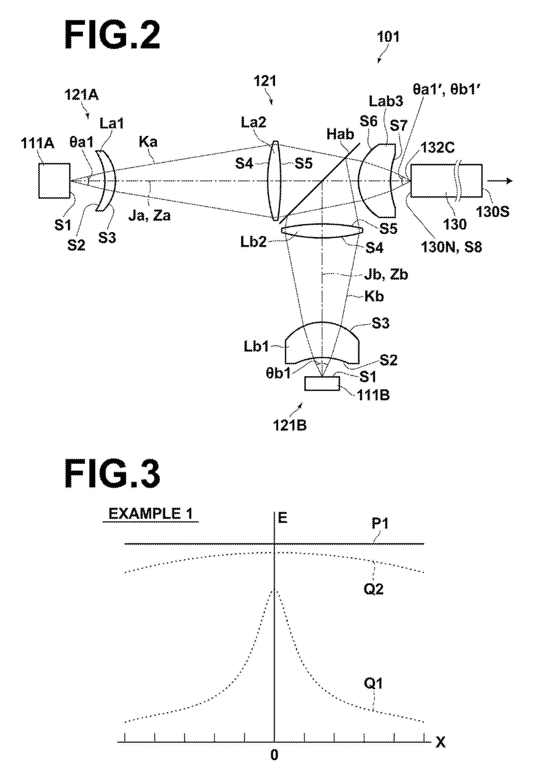
example 1
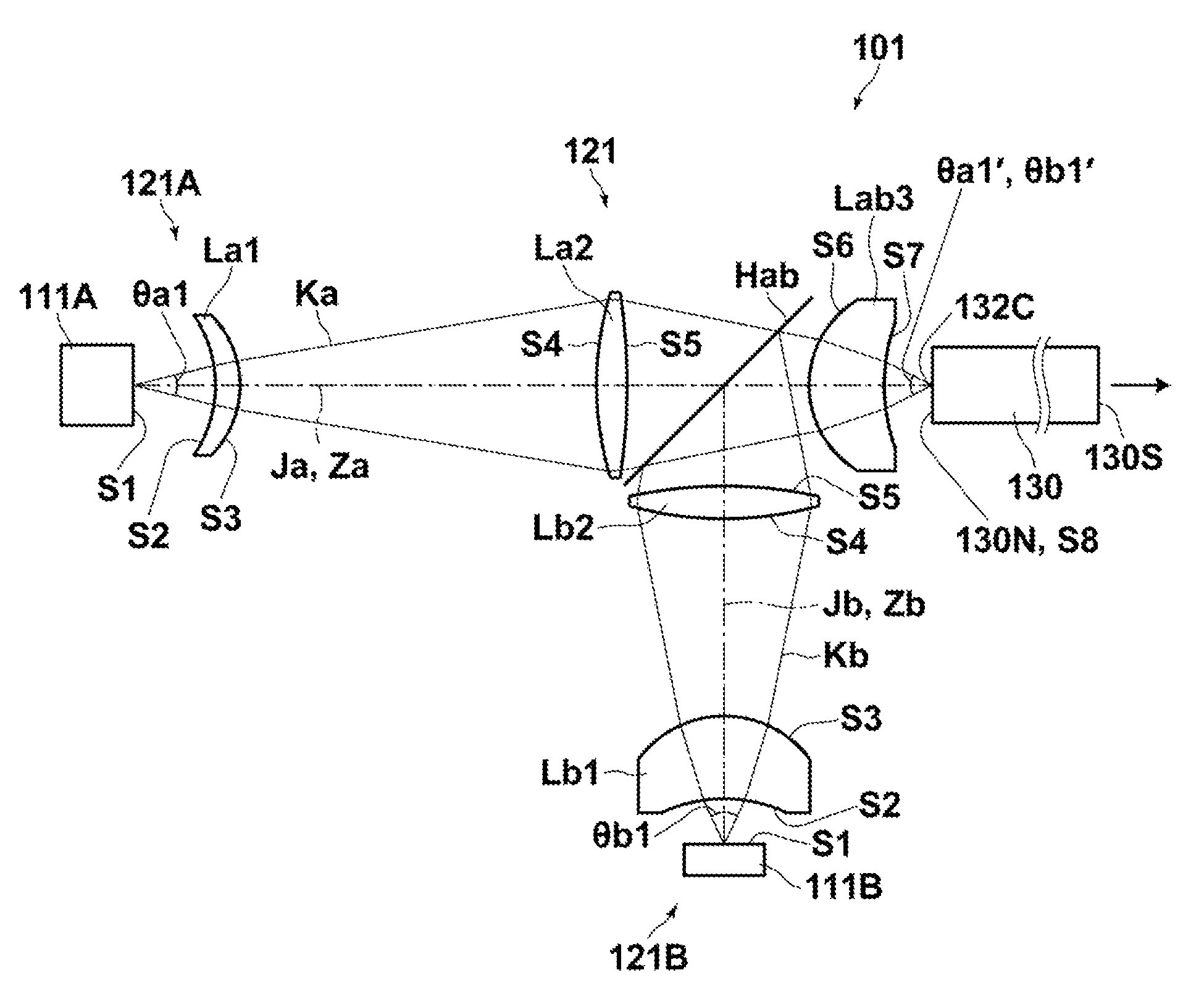
[0083]FIG. 2 is a sectional diagram that illustrates an illuminating optical system of Example 1. Example 1 is an illuminating optical system having a total of two light sources including one each of two types of light sources.
[0084]The illuminating optical system 101 of Example 1 illustrated in FIG. 2 has a first light source 111A and a second light source 111B, which are two different types of light sources, and a light combining optical system 121 that combines light beams output from the two light sources and causes them to converge at a single position.
[0085]Further, the illuminating optical system 101 is equipped with a rod integrator 130a that uniformizes the light intensity distributions of the light beams which are converged at the single position that enter a light input surface 130N at one end thereof and outputs a light beam, of which the light intensity distribution has been uniformized, from a light output surface 130S at a second end thereof.
[0086]The light combining ...
example 2
[0110]Next, Example 2 will be described.
[0111]FIG. 4 is a sectional diagram that illustrates an illuminating optical system 102 of Example 2. Note that constituent elements of Example 2 which are the same as those of Example 1 are denoted by the same reference numerals, and detailed descriptions thereof will be omitted.
[0112]The illuminating optical system 102 of Example 2 has a total of four light sources including two first light sources 112C of a first type, and two second light sources 112D of a second type.
[0113]Note that the light sources of the same type are those having at least light emitting regions of the same size, the same spreading angles of light beams output therefrom, and the same colors.
[0114]A light combining means 122 combines light beams output from the two first light sources 112C and the two second light sources 112D, and causes them to converge at a single position.
[0115]The light beams which are converged at the single position are caused to enter the rod in...
example 3
[0133]Next, Example 3 will be described.
[0134]FIG. 6 is a sectional diagram that illustrates an illuminating optical system 103 of Example 3. Note that constituent elements of Example 3 which are the same as those of Example 1 are denoted by the same reference numerals, and detailed descriptions thereof will be omitted.
[0135]The illuminating optical system 103 of Example 3 has a total of three light sources of three different types, which are a first light source 113E, a second light source 113F, and a third light source 113G.
[0136]A light combining means 123 combines light beams output from the first light source 113E, the second light source 113F, and the third light source 113G, and causes them to converge at a single position.
[0137]The light beams which are converged at the single position are caused to enter the light input surface 130N of the rod integrator 130.
[0138]The light combining optical system 123 has a first relay optical component set 123E that relays a light beam Ke...
PUM
 Abstract
Description
Claims
Application Information