
Balance stop device for watch pieces with tourbillon cage

a technology of a rotating tourbillon cage and a stop device, which is applied in the direction of mechanical time indication, frequency stabilisation mechanism, instruments, etc., can solve the problems of inability to stop the balance located in the rotating tourbillon cage and the oscillating therein, the synchronous adjustment of the time that is not accurate to the second, and the operation principle is relatively complicated both in the structure and the operation principle. , to achieve the effect of high versatility and advantageous

Active Publication Date: 2016-05-31
RICHEMONT INT
View PDF5 Cites 6 Cited by
  • Summary
  • Abstract
  • Description
  • Claims
  • Application Information

AI Technical Summary

Benefits of technology

The present invention aims to create a device for stopping the balance in a tourbillon of a timepiece that is space-saving, structurally simple, and reliable operating. The device comprises at least two pivotably mounted stop levers that can stop the balance in a quick and accurate manner, regardless of the position of the rotating mobile carriage of the tourbillon. The stop levers can act separately, ensuring that each stop lever acts on the balance in the stop position. The invention also relates to a movement module that can be used in a modular construction with a basic movement and offers versatility and advantageousness. The technical effects of the invention are space saving, simplicity, reliability, and accurate adjustment of the timepiece.

Problems solved by technology

However, it is difficult in the case of timepieces having a tourbillon to ensure a precise manual adjustment of the time since the tourbillon, respectively the balance mounted therein has to be stopped.
The balance located in the rotating tourbillon cage and oscillating therein thus cannot be stopped easily due to the columns of the mobile carriage which are forming an obstacle and are continuously rotating.
On the one hand, this has led to the use in some timepieces of movements having a tourbillon, however entirely without associated stop device for the balance, which in the corresponding timepieces results in the serious disadvantage of a synchronous adjustment of the time that is not accurate to the second.
This is, amongst others, the reason why most timepieces with a tourbillon cage visible from the dial side do not require a second hand, wherein however there is the above-mentioned disadvantage that it is not possible, due to the lack of a second hand and therefore the lack of a conventional second stop device, to adjust such tourbillon timepieces in a manner accurate to the second.
In addition, it shall also be noted here that a conventional second stop device for second hands known to the person skilled in the art, as described for example in document CH 220 530 (Thommens Uhrenfabriken AG), anyway cannot act as a stop device accurate to the second in timepieces designed in this way with a tourbillon because, as mentioned above, the balance, due to the construction, is arranged almost unattainably within the continuously rotating mobile carriage of the tourbillon.
This approach based on a double-arm spring requires a lot of space for the pivoting motion of the double-arm spring and is relatively complicated both in terms of the structure and of the operating principle.
However, the tourbillon per se must be changed as a result of this approach by the addition of further components, without any gain in terms of the simplicity and reliability of the mechanism.
Due to the short lever arm, however, the stop force exerted on the axis by the stop pliers has to be selected to be very high, wherein it may additionally take a comparatively long time to stop the balance.

Method used


Image

  • Balance stop device for watch pieces with tourbillon cage
  • Balance stop device for watch pieces with tourbillon cage
  • Balance stop device for watch pieces with tourbillon cage

Examples


first embodiment

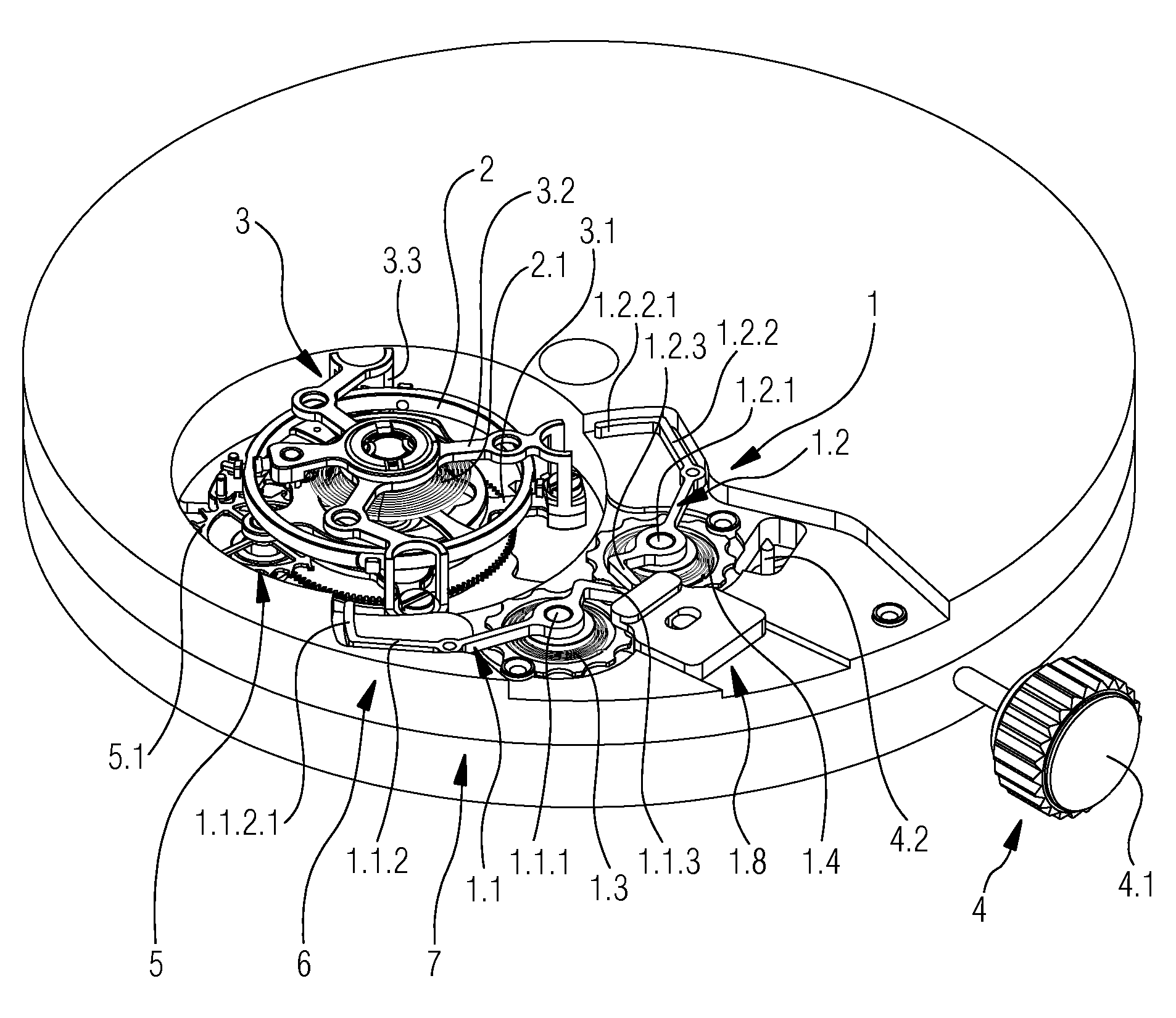
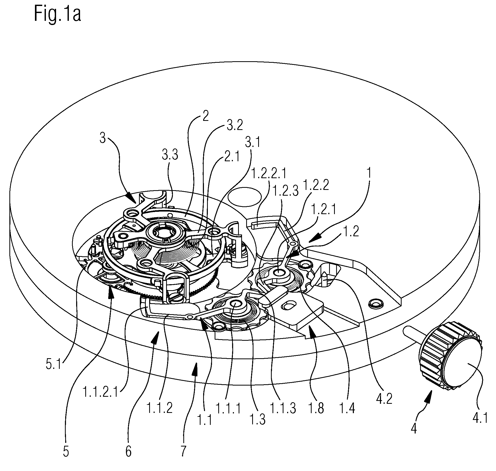
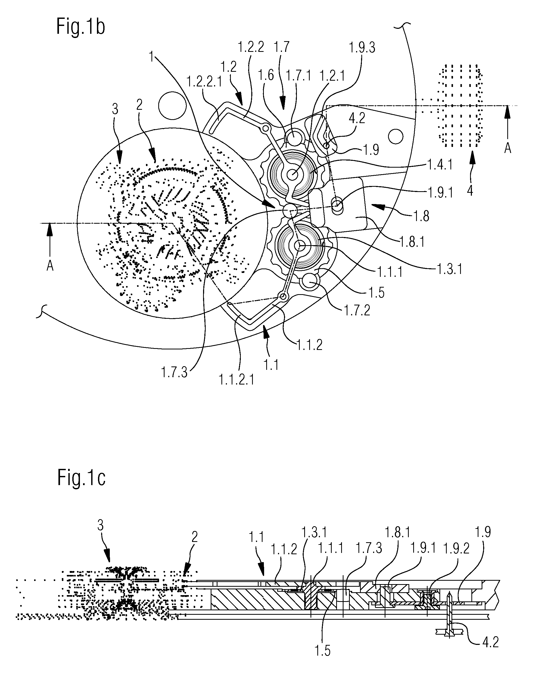
[0026]FIG. 1a is a perspective view of a movement module 7 built on a basic movement 6, said movement module comprising a tourbillon 3, as well as a device 1 according to the invention for stopping a balance 2 mounted in a tourbillon 3.

[0027]The tourbillon 3 per se in principle is already known and can be formed differently in detail. As is usual, it carries a balance 2, a spiral spring 2.1 belonging to the balance 2, and all parts of the escapement 5, such as the escape wheel 5.1 and the pallets, between the tourbillon lower part 3.1, the upper part 3.2 and the columns 3.3 arranged therebetween. Not all of these parts are visible or illustrated in the drawings insofar as these are known in detail to a person skilled in the art as well as are irrelevant in the context of the present invention and therefore will not be described further hereinafter. For this reason the operating principle of a movement with tourbillon also will not be discussed in detail.

[0028]A device 1 according to...

second embodiment

[0042]Analogously to FIGS. 2a and 2b, FIGS. 4a and 4b by means of plan views schematically show the operating principle of a device 1 according to the invention for stopping a balance 2 mounted in a tourbillon 3. The device 1 integrated in a movement module 7 is again illustrated in its rest position in FIG. 4a, in which the setting crown 4.1 of the timepiece is also illustrated in its rest position. The balance 2 and the tourbillon 3 are freely rotatable in this position.

[0043]By pulling the setting crown 4.1 into one of the pulled positions thereof, in particular into the position for adjusting the time of the timepiece, the control lever 1.9, similarly to the first embodiment of the device 1, is pivoted by means of the engagement of the pin 4.2, which in turn leads to a pivoting motion of the pivot lever 1.8.2. This causes the release of the stop levers 1.1, 1.2, which swing into their stop position under the influence of the pre-load exerted by the spiral springs 1.3, 1.4. In FI...


PUM


Abstract

A device for stopping a balance of a regulating organ mounted in a tourbillon of a timepiece. The device can be controlled by a setting device of the timepiece. The device includes at least two stop levers which are each secured pivotably to a respective lever pivot axis in such a manner that they can be brought from a rest position, in which the balance and the tourbillon are freely rotatable into a stop position, in which at least one of the stop levers acts via its free end on the balance such that the balance is stopped. The device additionally includes for each of these stop levers pre-loading structure, in such a manner that the force exerted onto the balance by each of the stop levers can act separately. The present invention also relates to a corresponding movement module equipped with such a device, respectively to a corresponding timepiece.

Description

PRIORITY CLAIM[0001]The present application is a National Phase entry of PCT Application No. PCT / EP2013 / 068141, filed Sep. 3, 2013, which claims priority from European Patent Application Number 12182743.0, filed Sep. 3, 2012, the disclosures of which are hereby incorporated by reference herein in their entirety.FIELD OF THE INVENTION[0002]The present invention relates to a device for stopping a balance of a regulating organ, said balance being mounted in a tourbillon of a timepiece, wherein the device can be controlled by means of a setting device of the timepiece, as well as to a corresponding movement equipped with such a device, respectively to a timepiece comprising a movement of this type.BACKGROUND OF THE INVENTION[0003]Mechanical timepieces with complex structure and more elaborated functions, in particular also in terms of driving and regulation of the movement, are popular and are becoming increasingly widespread. Tourbillons are to be regarded in this context as well since...

Claims


Application Information

Patent Timeline
Patent Type & Authority Patents(United States)
IPC IPC(8): G04B17/28G04B27/02
CPCG04B17/28G04B17/285G04B27/02
Inventor DONZE, EDOUARD
Owner RICHEMONT INT
Learn More