

Axle and vehicle comprising at least one such axle
- Summary
- Abstract
- Description
- Claims
- Application Information
AI Technical Summary
Benefits of technology
Problems solved by technology
Method used
Image

Examples
Embodiment Construction
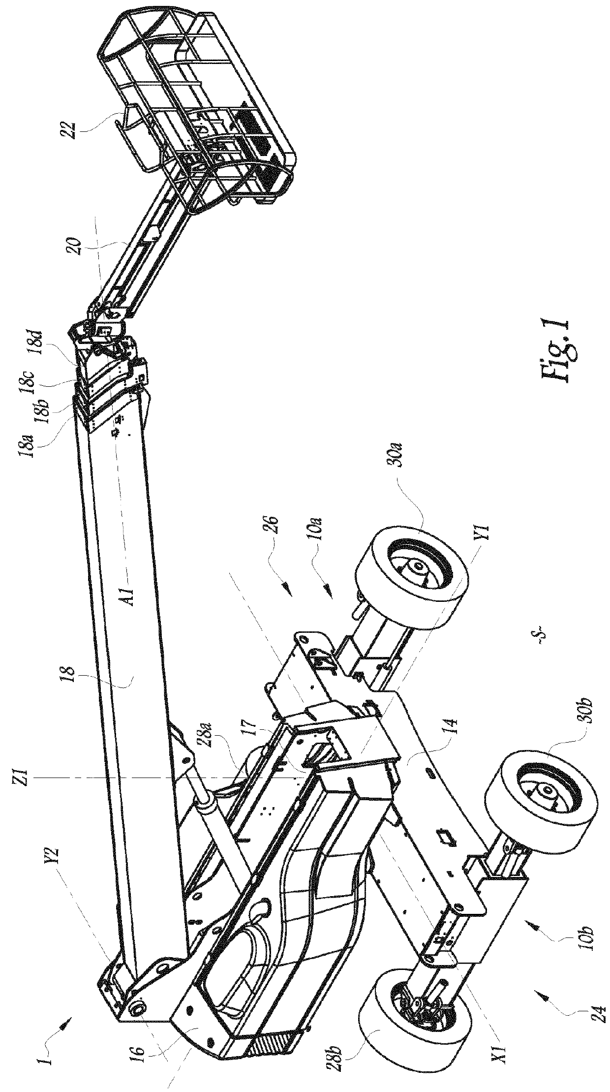
[0030]FIGS. 1 to 8 show a vehicle 1 of the aerial lifttype according to the invention.
[0031]The lift 1 is equipped with two axles 10a, 10b, also according to the invention, mounted on a motorized chassis 14. The chassis 14 has a globally parallelepiped shape. The motor means of the chassis 14, not shown, can comprise an internal combustion engine or an electric motor. An electronic central management unit, a hydraulic reservoir, a fuel tank and / or a set of electric batteries can also be mounted on the chassis 14.
[0032]In the rest of the description, the terms “horizontal”, “vertical”, “top” and “bottom” are defined relative to a surface area S. Reference X1 denotes the central longitudinal axis of the chassis 14 and Y1 denotes the central transverse axis of the chassis 14, perpendicular to the axis X1.
[0033]As illustrated in FIG. 1, a turret 16 able to rotate 360 degrees around a vertical axis of rotation Z1 is arranged on the chassis 14. Preferably, the turret 16 is actuated by hyd...
PUM
 Abstract
Description
Claims
Application Information