Head mounted display device and control method for head mounted display device
- Summary
- Abstract
- Description
- Claims
- Application Information
AI Technical Summary
Benefits of technology
Problems solved by technology
Method used
Image

Examples
second embodiment
B. Second Embodiment
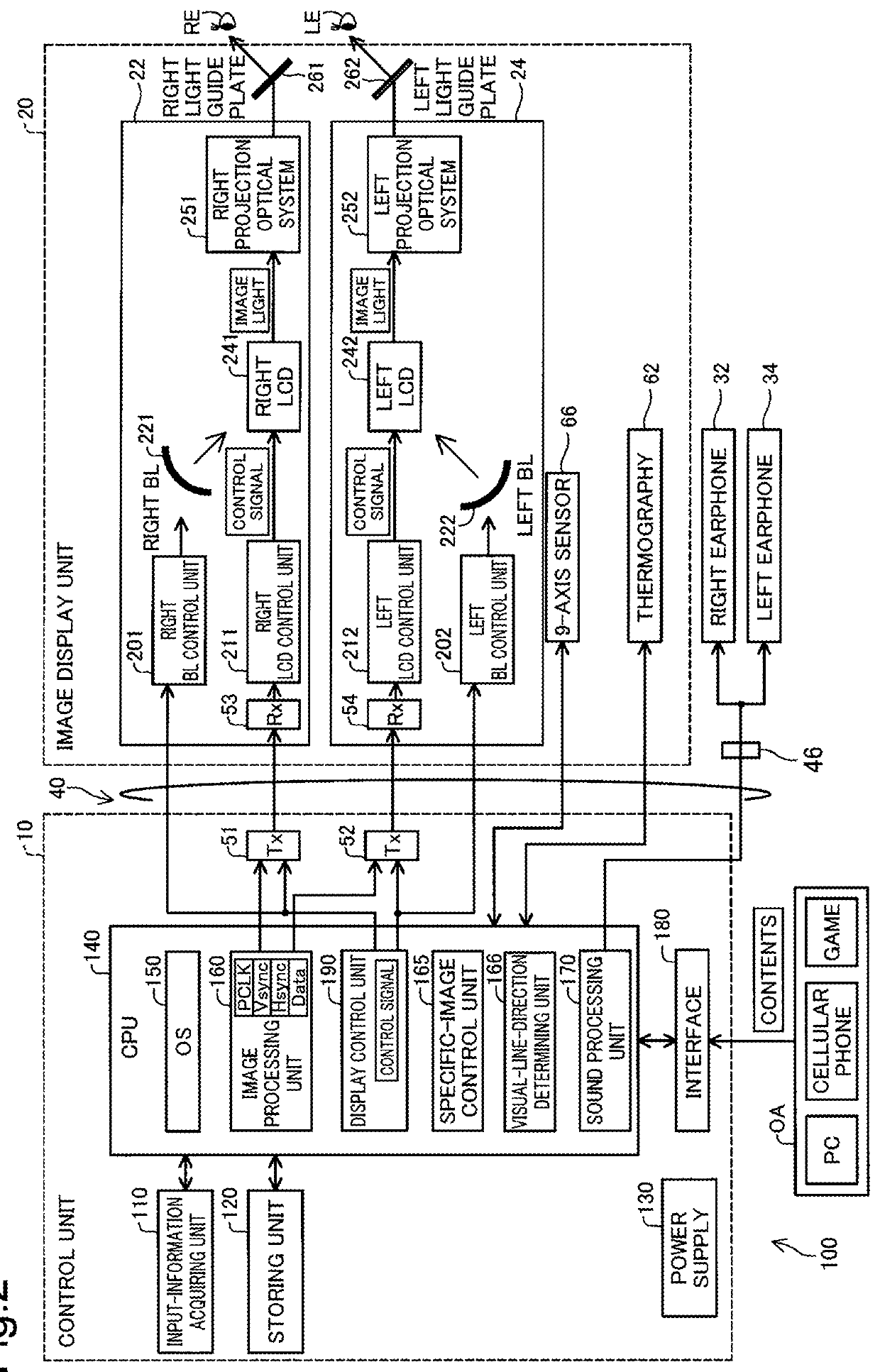
[0120]FIG. 11 is a block diagram functionally showing the configuration of a head mounted display device 100a in a second embodiment. The head mounted display device 100a is different from the head mounted display device 100 in the first embodiment in that a camera 61 is formed in an image display unit 20a instead of the thermography 62 and a GPS module 134, a radio communication unit 132, and an image determining unit 168 are formed in a control unit 10a. The other components are the same.
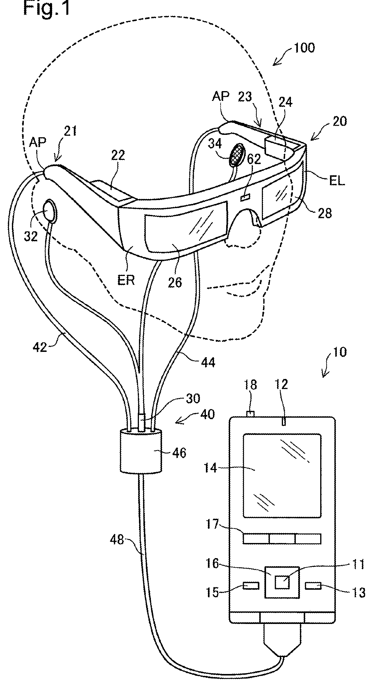
[0121]Like the thermography 62, the camera 61 is arranged in a position corresponding to the middle of the forehead of a user when the user wears the image display unit 20a. The camera 61 picks up an image of an outside scene, which is a scene on the outside of a visual line direction of the user, and acquires an outside scene image. The camera 61 is a monocular camera but may be a stereo camera. The camera 61 is equivalent to an image pickup unit in the appended claims.
[0122]T...
third embodiment
C. Third Embodiment
[0132]In a third embodiment, specific image display processing and specific image changing processing for changing a specific image according to a detection condition are performed according to a detection application different from the detection application in the embodiment explained above. In explanation in the third embodiment, a work support application for performing work support for a user is selected as the detection application.
[0133]FIG. 15 is an explanatory diagram showing the configuration of the external appearance of a head mounted display device 100d in the third embodiment. As shown in FIG. 15, the head mounted display device 100d is different from the head mounted display devices in the embodiments in that a right eye image pickup camera 37 and a left eye image pickup camera 38 are arranged in an image display unit 20d. The head mounted display device 100d is the same as the head mounted display devices in the embodiments in the other components. ...
modification 1
D1. Modification 1
[0153]In the embodiments, the fade-in display and the fade-out display are explained using the heat detection application and the weather application as the examples of the selected application. However, the detection application, the specific image, and the intermediate images can be variously modified.
[0154]FIGS. 23 and 24 are explanatory diagrams showing examples of intermediate images visually recognized by the user. In FIGS. 23 and 24, modifications of the intermediate images MI1 and MI2 (FIG. 7) in the first embodiment are shown. In FIGS. 23 and 24, intermediate images MI1a, MI2a, MI1b, and MI2b included in regions of the specific images SI1 and SI2 finally displayed on the image display unit 20 by the fade-in display are shown. In this modification, in the fade-in display, unlike the first embodiment, luminances are not gradually changed. After a plurality of intermediate images generated on the basis of different image data are displayed, the specific image...
PUM
 Abstract
Description
Claims
Application Information
 - R&D
- Intellectual Property
- Life Sciences
- Materials
- Tech Scout
- Unparalleled Data Quality
- Higher Quality Content
- 60% Fewer Hallucinations
Browse by: Latest US Patents, China's latest patents, Technical Efficacy Thesaurus, Application Domain, Technology Topic, Popular Technical Reports.
© 2025 PatSnap. All rights reserved.Legal|Privacy policy|Modern Slavery Act Transparency Statement|Sitemap|About US| Contact US: help@patsnap.com