Check patentability & draft patents in minutes with Patsnap Eureka AI!

Computer system and startup method

a computer system and startup method technology, applied in computing, instruments, electric digital data processing, etc., can solve the problems of os1 not being able to use a device driver of the external storage device, os2 cannot be started, and os1 may not be able to access the storage area in which the boot loader and the image file of the os2 are stored

Active Publication Date: 2016-06-07
HITACHI LTD
View PDF9 Cites 0 Cited by
  • Summary
  • Abstract
  • Description
  • Claims
  • Application Information

AI Technical Summary

Benefits of technology

The present invention provides a system and method for starting an operating system without direct involvement of another operating system. This is achieved by writing a hardware control unit and an operating system image in a memory area, and then rewriting address data to start the operating system. The system includes a first hardware control unit for controlling hardware and executing start processing of a first operating system, and a second hardware control unit for controlling hardware and executing start processing of a second operating system. The second operating system can be started without the direct involvement of the first operating system, and the address data is rewritten to allow for normal operation regardless of which storage area the second hardware control unit is written in. The technical effect of the invention is to provide a secure and flexible way to start multiple operating systems on a computer system.

Problems solved by technology

However, access by the OS1 to a storage area in which the boot loader and the image file of the OS2 are stored may be prohibited for security reasons.
Further, in a case where an image file of the OS1 and the image file of the OS2 are stored in different external storage devices, the OS1 may not be able to use a device driver of the external storage device, in which the image file of the OS2 is stored, because of an old kernel of the OS1 and other reasons.
As described above, there may be the cases where the OS2 cannot be started due to the limitations on the security and the hardware configuration.

Method used


Image

  • Computer system and startup method
  • Computer system and startup method
  • Computer system and startup method

Examples


first embodiment

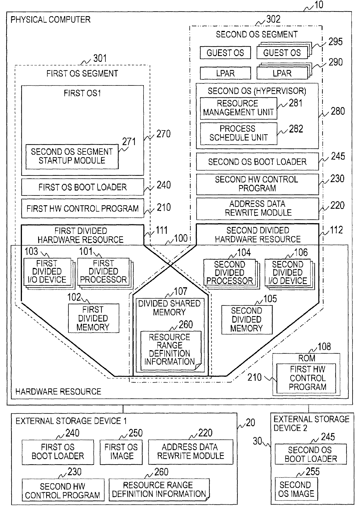
[0022]FIG. 1 is an explanatory view illustrating an example of the structure of a computer system according to a first embodiment of the present invention.

[0023]The computer system according to this embodiment is formed by a physical computer 10, a first external storage device 20, and a second external storage device 30. The physical computer 10 is coupled to the first external storage device 20 and the second external storage device 30 directly or via a network. A WAN, a LAN, or the like is conceivable as the network. Incidentally, the physical computer 10 may include a storage device in its inside.

[0024]The physical computer 10 is the computer on which an OS, executing predetermined processing, runs. According to this embodiment, it should be noted that two OSes, that is, a first OS 270 and a second OS 280, are assumed to run. Incidentally, the first OS 270 and the second OS 280 may employ either a general OS or a hypervisor which provides a virtualization function. In the follow...

modification example 1

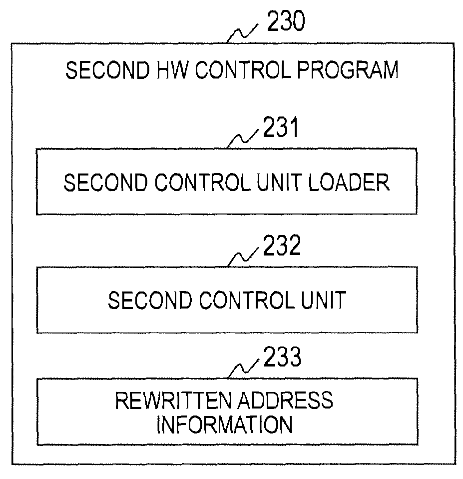
[0152]According to the first embodiment, the second HW control program 230 holds the rewritten address information 233, but the present invention is not limited to the above. In such a case, the processing of the step S201 is as follows.

[0153]The address data rewrite unit 221 refers to an execution form file of the second control unit loader 231 and, identifies the storage area in which the address data to be rewritten is included based on a relocation section (relocation information) included in the execution form file.

[0154]With regard to the execution form file of the second control unit loader 231, such a method may be employed that the file is stored in advance in the first external storage device 20 or the like, and is written in the second divided memory 105 by the first control unit 212.

[0155]The other processing is the same as that of the first embodiment, and hence a description thereof is omitted.

modification example 2

[0156]According to the first embodiment, the first control unit 212 writes the address data rewrite module 220 and the second HW control program 230 in the second divided memory 105, but the present invention is not limited to the above.

[0157]As another method, an arbitrary program that runs on the first OS segment 301 writes the address data rewrite module 220 and the second HW control program 230 in the second divided memory 105. In this case, the following processing is required for enabling temporary access to the second divided memory 105.

[0158]The arbitrary program generates a writable page table in a part of the storage area of the second divided memory 105 and, maps the part of the storage area of the second divided memory 105 into virtual memory space for the first OS 270 by referring to the page table.

[0159]After the address data rewrite module 220 and the second HW control program 230 are written in the second divided memory 105, the arbitrary program releases the mapping...


PUM


Abstract

A computer system comprising a plurality of computers on which a plurality of operating systems run, wherein a memory stores a first hardware control unit, wherein a storage device stores a first OS image, a second OS image, a second hardware control unit for executing start processing of the second OS, and an address rewrite unit, wherein the second hardware control unit includes a start unit for starting the second hardware control unit, wherein the address rewrite unit which is started by the first OS is configured to: obtain an address of a storage area, in which address data to be rewritten is stored, as a target address, rewrite the address data stored in the storage area corresponding to the obtained target address and start the start unit, wherein the start unit is configured to start the second hardware control unit by using the rewritten address data.

Description

CLAIM OF PRIORITY[0001]The present application claims priority from Japanese patent application JP 2013-124391 filed on Jun. 13, 2013, the content of which is hereby incorporated by reference into this application.BACKGROUND OF THE INVENTION[0002]The present invention relates to a computer system in which a plurality of OSes run on one computer, and a startup method of the computer.[0003]In recent years, attention has been given to the technique of starting two or more OSes (operating systems) on one physical computer, in order to make efficient use of hardware resources on the physical computer. Refer to, for example, Japanese Patent Application Laid-open No. Hei 11-149385 and WO 2009 / 113394.[0004]Japanese Patent Application Laid-open No. Hei 11-149385 discloses a “multi-operating system computer that alternately operates, as an operating OS, a first OS (operating system) for executing a plurality of tasks, to which priorities are assigned, in order of the priorities, and a second ...

Claims


Application Information

Patent Timeline
Patent Type & Authority Patents(United States)
IPC IPC(8): G06F9/44G06F9/455G06F9/45
CPCG06F9/441G06F9/4406G06F9/45533
Inventor HAYAKAWA, NORIMITSUYOSHIDA, KEISUKESHIMOJO, TAKASHIKONAGAYA, MASATOSHINAKAGAWA, YOSHIHITOMORIKI, TOSHIOMI
Owner HITACHI LTD
Features
  • R&D
  • Intellectual Property
  • Life Sciences
  • Materials
  • Tech Scout
  • Unparalleled Data Quality
  • Higher Quality Content
  • 60% Fewer Hallucinations
Learn More