
Scroll compressor and processing method of scroll including a projection on a tip seal and a hole in a tip seal groove

a processing method and compressor technology, applied in the field of scroll compressors, can solve problems such as problems, achieve the effect of compact size of scroll compressors, simple processing, and ensure mass production

Active Publication Date: 2016-06-14
MITSUBISHI HEAVY IND THERMAL SYST
View PDF30 Cites 0 Cited by
  • Summary
  • Abstract
  • Description
  • Claims
  • Application Information

AI Technical Summary

Benefits of technology

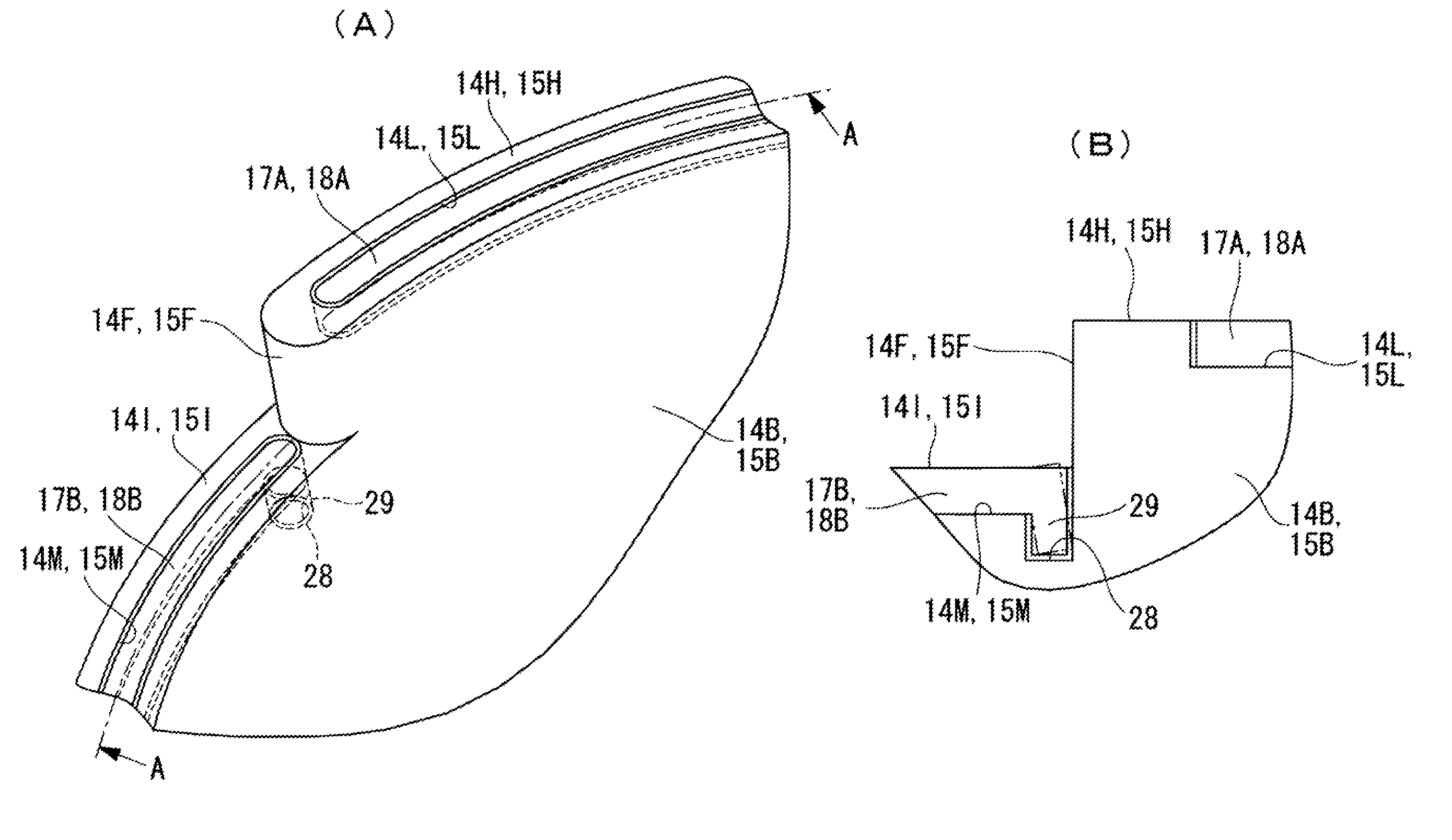
[0038]According to the scroll compressors pertaining to the above-described aspects of the present invention, even if one end of the tip seal provided on the tip surface of the spiral wrap is installed so as to extend to the position where it becomes in non-contact with the bottom land of the corresponding scroll by a revolution in an orbiting manner of the orbiting scroll, and becomes in a cantilever state, an extracted state from the tip seal groove due to bend of one end of the tip seal that has become in a cantilever state can be prevented by means of fitting and engaging of the projection and the hole that are respectively provided at the one end of the tip seal and in one end bottom surface of the tip seal groove, and thus the tip seal can be installed to the edge of the end side of the tip surface, the installation area of the tip seal is enlarged, thereby gas leak from the tip surface is decreased, and further improvement in efficiency and in performance of the stepped wrap scroll compressor can be achieved. Particularly, the performance improvement effect under the condition where the suction pressure is high at the time of low rotation is remarkable, and further compactness in size of the stepped wrap scroll compressor can be achieved. In addition, even if the tip seal is installed extending to the end as described above, the bite breakage accident etc. due to an extracted state of the end can be reliably prevented. Furthermore, an extracted state prevention means can be configured with the projection and the hole in the vertical direction that are respectively provided on the back surface of the tip seal and in the bottom surface of the tip seal groove, they can be simply processed, and thus mass production can be sufficiently secured.
[0039]In addition, according to the scroll compressors pertaining to the above-described aspects of the present invention, the integrated tip seal can be installed so as to cover the whole area of the inner circumferential side and the outer circumferential side that sandwich the step of the tip surface of the spiral wrap by fitting the crank-shaped integrated tip seal integrated through the connection portion over the step to the tip seal groove continuously provided in the higher and the lower tip surfaces over the step. In addition, the outer circumferential end portion that repeats contact and non-contact with the bottom land of the other scroll of the tip seal portion that is fitted in the tip seal groove of the lower tip surface is supported by the connection portion over the step, and thereby an extracted state due to bend of the end portion can be prevented. Furthermore, since the force in the tip seal groove direction applied to the tip seal portion fitted in the tip seal groove of the higher tip surface can be received by means of fitting and engaging of the projection and the hole that are respectively provided at the position near the step and in the bottom surface of the position near the step of the tip seal groove, the tip seal is installed in the whole area of the inner circumferential side and the outer circumferential side that sandwich the step of the tip surface of the spiral wrap, and the installation area of the tip seal is enlarged, whereby gas leak from the tip surface is decreased, and further improvement in efficiency and in performance of the stepped wrap scroll compressor can be achieved. Particularly, the above-described aspects have an effect in performance improvement under the condition where the suction pressure is high at the time of low rotation, and further compactness in size of the stepped wrap scroll compressor can be achieved. In addition, by installing the integrated tip seal as described above, can be prevented the bite breakage accident etc. due to an extracted state of the outer circumferential end portion of the integrated tip seal installed in the tip seal groove of the lower tip surface, and can be prevented the breakage accident etc. of the connection portion of the integrated tip seal due to the force in the groove direction that is applied to the tip seal portion fitted in the tip seal groove of the higher top land. Furthermore, in this case, an extracted state of the tip seal portion of the lower top land side can be supported by the connection portion of the integrated tip seal, a fitting portion is not needed other than the projection and the hole in the vertical direction that are respectively provided on the tip seal and in the tip seal groove that are provided on the higher tip surface side, they can be easily processed, and thus mass production can be sufficiently secured.
[0040]In addition, according to the processing methods of the scroll pertaining to the above-described aspects of the present invention, when the end of the tip seal becomes in a cantilever state by a revolution in an orbiting manner of the orbiting scroll, processing of the tip seal groove including the hole that prevents an extracted state due to bend of the end can be simultaneously performed only by using the same end mill, and moving the end mill in the depth direction of the hole at the hole position, and thus the tip seal groove of the fixed and the orbiting scrolls that include the hole can be efficiently processed, and reduction in productivity due to perforating the hole can be suppressed to the minimum.

Problems solved by technology

At this time, there is a possibility that the tip seal becomes in a cantilever state to be bent, thereby becomes an extracted state from a seal groove to be caught by the step, and may become broken.
At this time, there is a possibility that the tip seal becomes in a cantilever state to be bent, thereby becomes an extracted state from the seal groove to be caught by the discharge port, and that a similar problem may occur.

Method used


Image

  • Scroll compressor and processing method of scroll including a projection on a tip seal and a hole in a tip seal groove
  • Scroll compressor and processing method of scroll including a projection on a tip seal and a hole in a tip seal groove
  • Scroll compressor and processing method of scroll including a projection on a tip seal and a hole in a tip seal groove

Examples


first embodiment

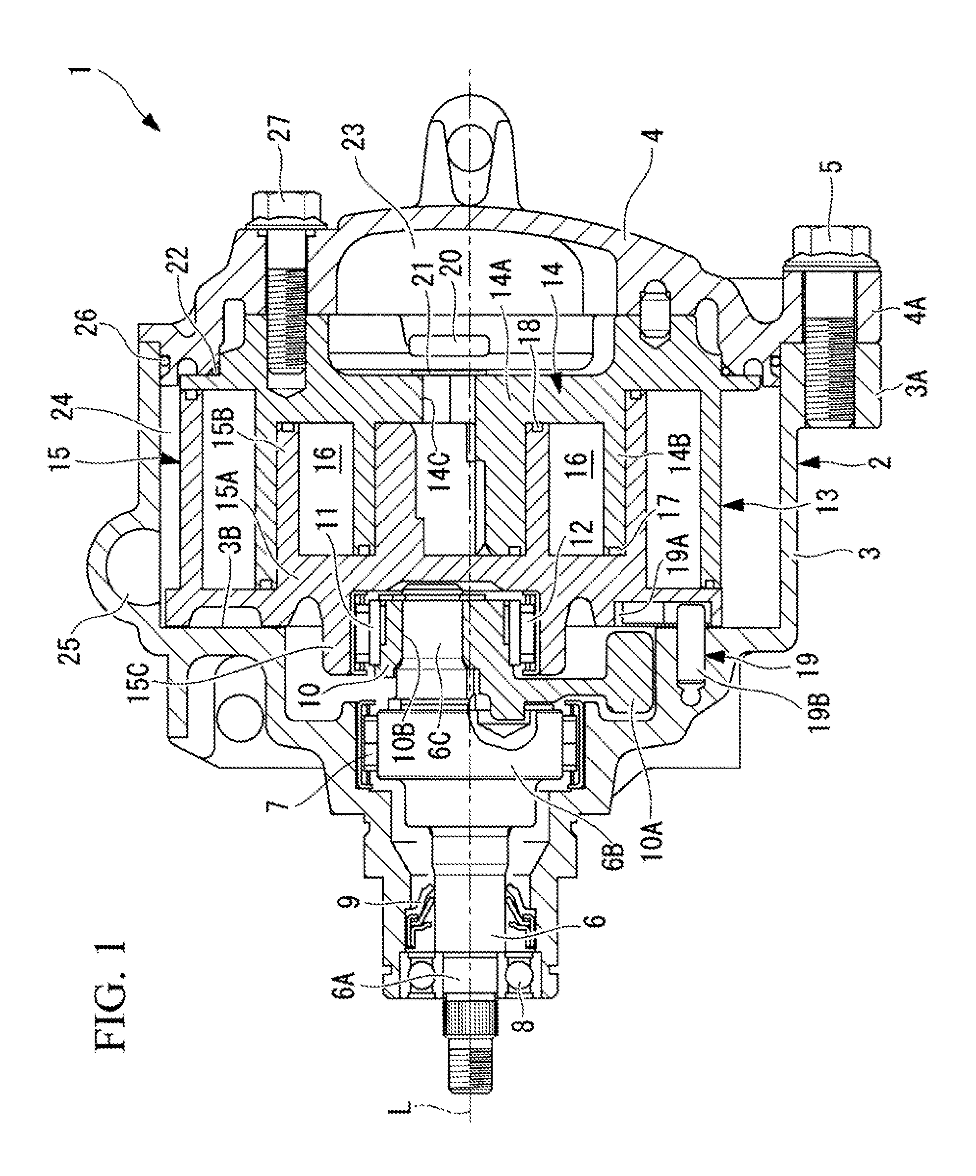
[0048]Hereinafter, a first embodiment of the present invention will be described using FIGS. 1 to 3.

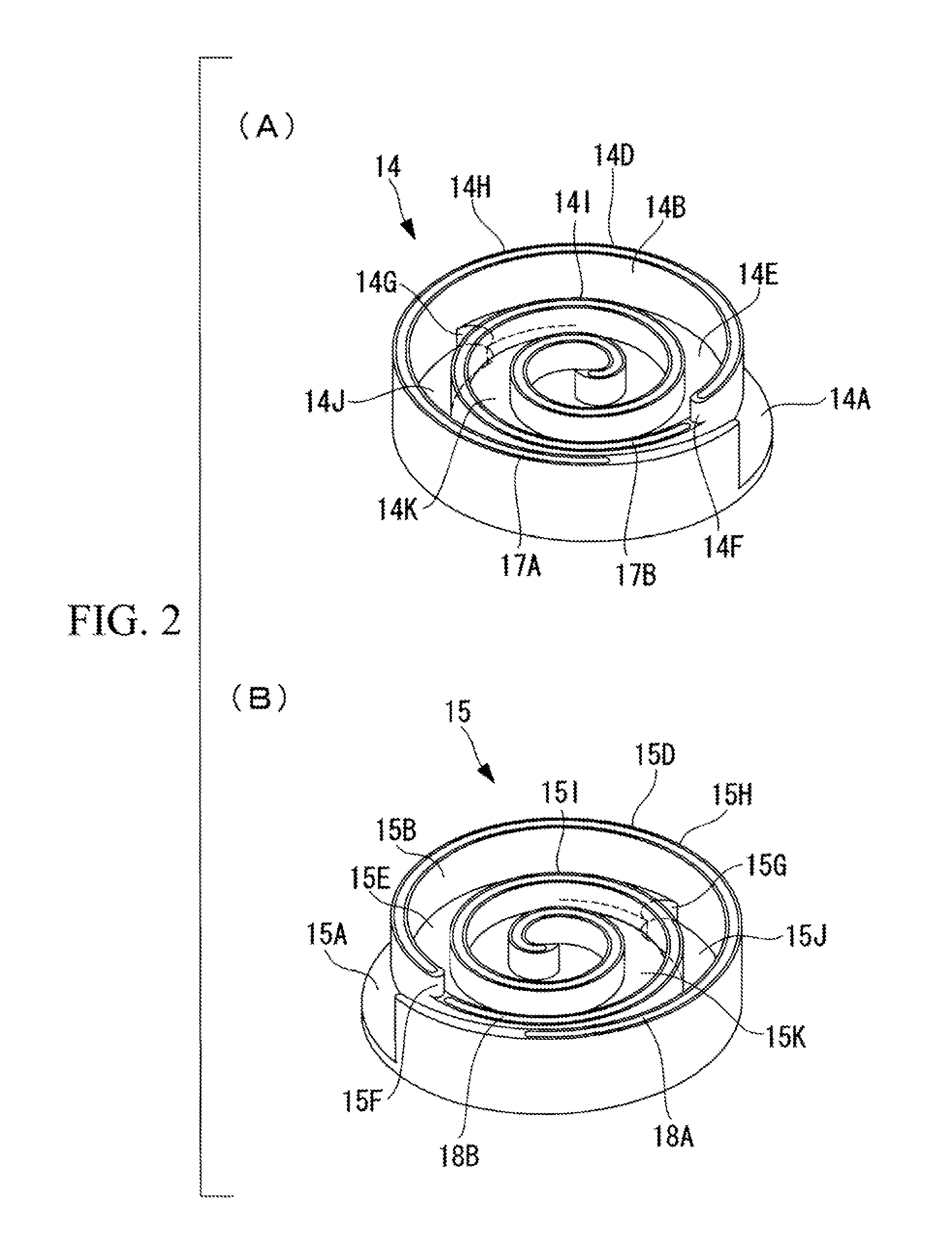
[0049]FIG. 1 shows a longitudinal sectional view of a scroll compressor pertaining to the first embodiment of the present invention, FIG. 2A a perspective view of a fixed scroll of the scroll compressor, and FIG. 2B a perspective view of an orbiting scroll thereof.

[0050]A scroll compressor 1 has a housing 2 constituting a shell, and the housing 2 is configured by integrally tightening and fixing a front housing 3 and a rear housing 4 by means of a bolt 5.

[0051]In the front housing 3 and the rear housing 4, flanges 3A and 4A for tightening are integrally formed at a plurality of points (for example, four points) on circumferences thereof at regular intervals, and the front housing 3 and the rear housing 4 are integrally combined with each other by tightening the flanges 3A and 4A by means of the bolt 5. Inside the front housing 3, a crankshaft (drive shaft) 6 is rotatably supported aro...

second embodiment

[0082]Next, a second embodiment of the present invention will be described using FIGS. 4A, 4B, and 4C.

[0083]The embodiment is different from the above-described first embodiment in a point where the tip seals 17A and 18A, and 17B and 18B that are provided on the higher tip surfaces 14H and 15H and the lower tip surfaces 14I and 15I are integrated to be as the integrated tip seals 17 and 18. Since the other points excluding the following are similar to in the first embodiment, description of the points will be omitted.

[0084]In the embodiment, the tip seals 17A and 18A, and 17B and 18B that are installed on the higher tip surfaces 14H and 15H and the lower tip surfaces 14I and 15I of the spiral wraps 14B and 15B are made as the crank-shaped integrated tip seals 17 and 18 that have been integrated through connection portions 17C and 18C over the steps 14F and 15F.

[0085]In addition, the tip seal grooves 14L and 15L, and 14M and 15M that are provided in the higher tip surfaces 14H and 15...

third embodiment

[0100]Next, a third embodiment of the present invention will be described using FIGS. 5A and 5B.

[0101]The embodiment is different from the above-described first and second embodiments in a point where a projection 34 and a hole 35 are respectively provided on the tip seals 17A and 18A that are provided on the higher tip surfaces 14H and 15H, and in an outer circumferential end of the tip seal grooves 14L and 15L. Since the other points are similar to in the first and second embodiments, description thereof will be omitted.

[0102]In the embodiment, as shown in FIGS. 5A and 5B, the cylindrical hole 35 with a diameter equal to the groove width dimension of the tip seal grooves 14L and 15L is formed in the vertical direction in the outer circumferential end of a bottom surface of the tip seal grooves 14L and 15L that are provided in the higher tip surfaces 14H and 15H of the spiral wraps 14B and 15B. Meanwhile, the embodiment is configured such that the cylindrical projection 34 with a d...


PUM

PropertyMeasurementUnit
heightaaaaaaaaaa
diameteraaaaaaaaaa
widthaaaaaaaaaa

Abstract

In a scroll compressor of the present invention, tip seals and are fitted in tip seal grooves provided in higher and lower tip surfaces of spiral wraps. One end of the tip seals then repeats contact and non-contact with a bottom land of the other scroll by a revolution in an orbiting manner of an orbiting scroll. In addition, a projection extending in a vertical direction from a back surface of the tip seals is provided at one end of the tip seals that become in a cantilever state. Furthermore, a hole in which the projection is fitted and engaged is formed in one end bottom surface of the tip seal grooves in which the tip seals are fitted.

Description

CROSS REFERENCE TO RELATED APPLICATIONS[0001]This application is based on Japanese Patent Application No. 2012-067168, with a filing date of Mar. 23, 2012, which is hereby incorporated by reference herein in its entirety.TECHNICAL FIELD[0002]The present invention relates to a scroll compressor in which a step is provided in an arbitrary position along a spiral direction of a fixed scroll and an orbiting scroll, and a processing method of the scroll.BACKGROUND ART[0003]In the technical field of scroll compressors, there has been a so-called stepped wrap scroll compressor in which a step is respectively provided at an arbitrary position along a spiral direction of both of a tip surface and a bottom land of a spiral wrap of each of a fixed scroll and an orbiting scroll, and in which a wrap height of an outer circumferential side of the spiral wrap relative to the step is made higher than a wrap height of an inner circumferential side thereof relative to the step. Since the scroll compr...

Claims


Application Information

Patent Timeline
Patent Type & Authority Patents(United States)
IPC IPC(8): F04C18/02F04C18/00F04C27/00
CPCF04C18/00F04C18/0215F04C18/0276F04C18/0284F04C27/005Y10T29/4924F01C1/02F04C18/02F04C27/02
Inventor HIRATA, HIROFUMIKUWAHARA, TAKAYUKI
Owner MITSUBISHI HEAVY IND THERMAL SYST
Learn More